In recent years, there are more and more car theft cases, which bring huge economic losses to people. Various car anti-theft devices have appeared on the market. This car anti-theft system uses the STM32F103R6T6 (hereinafter referred to as STM32F103) microcontroller produced by ST as the controller, which has powerful functions and good real-time performance.
1 System structure and function
The car remote anti-theft system is designed based on modern wireless communication technology. It can send the car status information directly to the owner's mobile phone without being restricted by distance, and perform one-to-one anti-theft alarm. The structure of the car remote anti-theft system is shown in Figure 1.
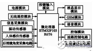
The information collection module of the car anti-theft system includes human body sensing sensors, vibration sensors, etc., which are used to collect car alarm information. The sensor will collect the alarm information and transmit it to the microprocessor for processing, and the microprocessor will start to execute the alarm program. First, a text message is sent to the car owner's mobile phone; then, the alarm will issue a voice warning according to different alarm situations. For example, if someone enters the car, the alarm will issue a voice alarm of "You have entered the car, please leave."
The car owner can send instructions to check the status of the car at any time.
When the anti-theft device is armed, the system controls the rearview mirror to fold; when it is disarmed, the system controls the rearview mirror to unfold.
The LCD display part is used to display the angle value set by the owner.
The wireless remote control is used to arm and disarm the system.
2 System Hardware Design
2.1 MCU Minimum System
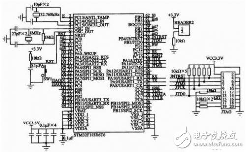
The minimum system of STM32F103 is shown in Figure 2, which consists of STM32F103 microcontroller, crystal oscillator circuit, JTAG interface and reset circuit. The enhanced STM32F103 microcontroller is based on the high-performance ARM Cortex-M3 (32-bit RISC core), with built-in 32 KB Flash and 10 KBSRAM, 64 enhanced I/O ports, and 2 USARTs. STM32F103 adopts 64-pin LQFP package, the power supply voltage is 2.0~3.6 V, the power saving mode ensures low power consumption requirements, and has high cost performance. The microcontroller adopts 32.768kHz and 8 MHz external crystal oscillators to provide accurate clock source and working clock respectively; the reset circuit is designed to combine key reset and power-on automatic reset. The application of STM32F103 chip improves the execution efficiency of the whole system, enhances the system stability, and reduces power consumption and production cost.
2.2 Information Collection Module
The information acquisition module mainly includes a human body sensor, a vibration sensor and a rearview mirror angle acquisition circuit. The human body sensor mainly detects whether a car thief has entered the car to steal, and the data output terminal is connected to the PC10 pin of the microcontroller. When the car is hit, smashed, shaken or pulled, the vibration sensor detects the relevant information and sends it to the PB0 pin of the microcontroller for processing.
In the car anti-theft system, the PC4 and PC5 pins of STM32F103 receive the input data of the left and right angle sensors respectively, and convert the analog voltage into digital quantity through the A/D conversion function of the PCA and PC5 pins and display it on the LCD1602. [page]
2.3 GSM Module
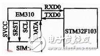
The GSM module uses Huawei's EM310. EM310 GSM supports serial interface, communicates with the outside world via UART interface, connects to the RXD0 and TXD0 pins of the STM32F103 microcontroller, and is controlled by AT instructions. UART supports programmable data width, programmable data stop bit, programmable parity check or no check. The highest supported baud rate is 115.2 kb/s and the lowest supported baud rate is 300 b/s. The default supported rate is 9 600 b/s, and the baud rate can be saved after power failure. The GSM module has a standard SIM card interface. The GSM module connection circuit diagram is shown in Figure 3.
2.4 WT588D Voice Module
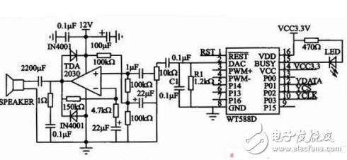
This system uses the WT588D voice module with 32 Mb memory. When sampling at 8 kHz, the recording time is up to 790 s, which meets the requirements of voice reminders. In the alarm system, voice reminders require higher decibels. In order to drive high-power speakers, the output is connected to the power amplifier in the form of DAC. The circuit diagram of the WT588D voice module is shown in Figure 4. R1 and C1 are connected in parallel to the ground amplifier. The power amplifier uses TDA2030, which has a rated power of 14 W, high cost performance and wide application. The connection between the voice module and the microcontroller adopts a 3-wire serial port control mode. Unlike the standard 4-wire SPI, the WT588D only receives data, instructions and clock signals sent by the microcontroller, and does not need to send data. In this 3-wire serial port mode, P01 is the DATA data interface, P02 is the chip select CS, and P03 is the CLK clock, which are connected to PC7, PC8, and PC6 of the microcontroller respectively. The module supply voltage is 2.8~3.6 V, and 3.3 V is selected. BUSY is the busy signal output terminal. When the output is low level, the light-emitting diode is on, and it is in the playback state. The WT588D module has a wide range of applications and can be applied to almost all voice places, such as station announcers, alarms, alarm clocks, smart home appliances and other automatic control applications.
2.5 Control module design
2.5.1 Oil control circuit
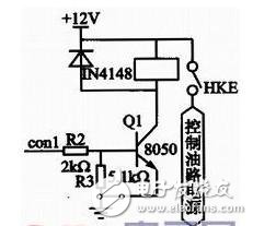
The specific method of controlling the automatic power off of the gasoline injection system power supply is to install a normally closed automobile power-off relay on the power line of the gasoline injection system to control the power supply of the gasoline injection system. The oil circuit control circuit is shown in Figure 5. R2 and R3 play the role of current limiting. When con1 is at a high level, Q1 is turned on and the relay is opened, thereby realizing power off and flameout. Under normal circumstances, when con1 outputs a low level, Q1 is turned off, the relay is closed, and the gasoline injection system power supply circuit is connected. When the relay coil changes from on to off, it will induce a large self-inductance electromotive force, which is easy to break down the transistor 8050. Therefore, a diode IN4148 is connected in reverse parallel at both ends of the relay to absorb the electromotive force and protect the transistor.
2.5.2 Rearview mirror control circuit
Each rearview mirror is controlled by a stepper motor and two buttons. The stepper motor is used to rotate the rearview mirror, and the two buttons are the angle increase button and the angle decrease button. The car owner uses the buttons to set the rearview mirror angle according to his own habits. When the system is armed, the rearview mirror is controlled to fold; when it is disarmed, the rearview mirror is controlled to unfold. Figure 6 is a drive circuit that controls the angle of one of the rearview mirrors.

The chip L298N has two power supplies, namely the working power supply and the driving power supply. VSS is the working power supply, with a voltage range of 4.5~36 V. This system uses a 5 V working voltage; VS is the driving voltage, with a maximum of 36 V. It is required that VS is preferably greater than VSS. 12 V is selected in the design. int1, int2, int3, and int4 are the input terminals of the microcontroller to control the motor, corresponding to the four outputs OUT1, OUT2, OUT3, and OUT4 respectively. The outputs are connected to the four-phase five-wire stepper motor. ISENA and ISENB are enable terminals, which are directly connected to the 5 V logic power supply. In other words, both motors are always in the enabled state. Since the motor we use is a coil type, when it suddenly switches from the running state to the stopped state and from the clockwise state to the counterclockwise state, a large reverse current will be formed. The role of adding a diode in the circuit is to discharge the reverse current when it is generated to protect the safety of the chip. Motorl provides a socket for the stepper motor. [page]
2.6 Wireless remote control module
The car remote anti-theft system does not require the owner to have close contact with the anti-theft device. The system can be armed and disarmed using a wireless remote control. When the owner is present, the anti-theft system can be disarmed to avoid misjudgment. After the owner leaves, the vehicle can be armed. The wireless remote control module uses the codec chip PT2262/PT2272 produced by Taiwan Pucheng Company, and the operating voltage range is 2.6~15 V. The remote control transceiver module is shown in Figure 7.
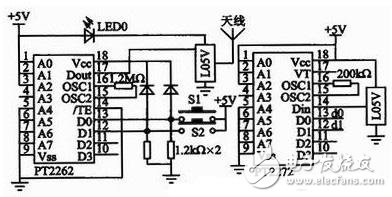
The transmitter PT2262 is equipped with two buttons S1 and S2 to arm and disarm the system respectively. When S1 is pressed, the D0 pin of PT2262 inputs a high level, and Dout transmits a code to PT2272; the corresponding D0 pin of the receiving PT2272 outputs a low level, and the microcontroller detects that the d0 terminal is low, the system enters the armed state, and each module starts working. The data outputs d0 and d1 of PT2272 are connected to PB10 and PB11 of the microcontroller. Each time a key is pressed, in the same system, Dout will output the same code, and the microcontroller will implement the user's arming and disarming needs based on the low level of the data output pin of the receiving module detected.
2.7 Power Module
The power supply voltage in the car is +12 V, and the voltages required by each module in the system are +5 V, +3.3 V and +4 V. Therefore, it is necessary to convert the +12 V voltage into +5 V, +3.3 V and +4 V voltages through a power conversion circuit. The LM2596 switching voltage regulator is used to convert +12 V to 5 V. The regulator has a fixed voltage output and an adjustable voltage output. Here, a +5 V fixed voltage output is selected, with an output current of up to 3 A, and has overheat protection and current limiting protection functions. On the basis of outputting +5 V voltage, the X1117 voltage regulator chip is used to convert the +5 V voltage into +3.3 V. The X1117 is a low-drop three-terminal linear voltage regulator circuit with positive voltage output. It can output fixed voltages of +1.5 V, +2.8 V, +3.3 V, etc., and can also output adjustable voltages. The difference between the input and output voltages of the X1117 cannot be too large to avoid excessive heat dissipation and damage to the device. The system reduces the +5 V voltage by about 0.7 V through the diode IN4007 to obtain the voltage required by the EM310 module. The power supply circuit is shown in Figure 8.

3 System Software Design
The system uses C language to write programs, write the programs into the microcontroller, and perform system testing. This design writes the source program of STM32F103 in the MDK compilation environment, generates .hex program code after compilation, and uses the JTAG download line to download the .hex file to the Flash of the target microcontroller.
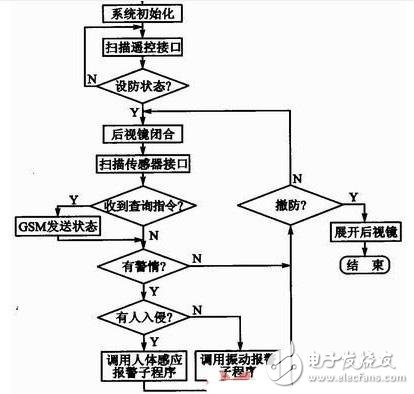
The overall program flow chart of the system is shown in Figure 9. After the main controller STM32F103 is initialized, the system detects whether it is in the armed state. The remote controller PT2262/PT2272 does not require software coding, but only needs to detect whether the receiving module has received the armed control. If the system is not in the armed state, the program executes a cycle of controlling the rearview mirror and scanning the remote control interface. If it is in the armed state, the rearview mirror is controlled to close and fold, and the system keeps monitoring the human body sensing module, vibration module and controller interface to collect alarm information at any time. If the owner queries the status of each interface through SMS at this time, the program calls the GSM communication program to send the status of each interface. If an alarm occurs, by detecting the microcontroller interface, it is determined whether the car is vibrating or someone is illegally intruding. Then, according to different situations, the human body sensing alarm subroutine or vibration alarm subroutine is called for corresponding processing. After that, the microcontroller scans the remote control interface to decide whether to continue to arm or disarm. If disarmed, the rearview mirror unfolds to the angle set by the owner.
Conclusion
This paper completes the overall design of the car remote anti-theft system based on STM32F103 microcontroller, and designs the system's software and hardware on this basis. After repeated tests, the system basically meets the expected requirements.
Previous article:Design of automobile taillight controller based on single chip microcomputer
Next article:Design of car wireless black box based on MG2455 microprocessor
Recommended ReadingLatest update time:2024-11-16 20:34


- Popular Resources
- Popular amplifiers
-
 The STM32 MCU drives the BMP280 absolute pressure sensor program and has been debugged
 -
 DigiKey \"Smart Manufacturing, Non-stop Happiness\" Creative Competition - Small Weather Station - STM32F103 Sensor Driver Code
 -
 LwIP application development practical guide: based on STM32
 -
 FreeRTOS kernel implementation and application development practical guide: based on STM32
 Professor at Beihang University, dedicated to promoting microcontrollers and embedded systems for over 20 years.
- Innolux's intelligent steer-by-wire solution makes cars smarter and safer
- 8051 MCU - Parity Check
- How to efficiently balance the sensitivity of tactile sensing interfaces
- What should I do if the servo motor shakes? What causes the servo motor to shake quickly?
- 【Brushless Motor】Analysis of three-phase BLDC motor and sharing of two popular development boards
- Midea Industrial Technology's subsidiaries Clou Electronics and Hekang New Energy jointly appeared at the Munich Battery Energy Storage Exhibition and Solar Energy Exhibition
- Guoxin Sichen | Application of ferroelectric memory PB85RS2MC in power battery management, with a capacity of 2M
- Analysis of common faults of frequency converter
- In a head-on competition with Qualcomm, what kind of cockpit products has Intel come up with?
- Dalian Rongke's all-vanadium liquid flow battery energy storage equipment industrialization project has entered the sprint stage before production
- Allegro MicroSystems Introduces Advanced Magnetic and Inductive Position Sensing Solutions at Electronica 2024
- Car key in the left hand, liveness detection radar in the right hand, UWB is imperative for cars!
- After a decade of rapid development, domestic CIS has entered the market
- Aegis Dagger Battery + Thor EM-i Super Hybrid, Geely New Energy has thrown out two "king bombs"
- A brief discussion on functional safety - fault, error, and failure
- In the smart car 2.0 cycle, these core industry chains are facing major opportunities!
- The United States and Japan are developing new batteries. CATL faces challenges? How should China's new energy battery industry respond?
- Murata launches high-precision 6-axis inertial sensor for automobiles
- Ford patents pre-charge alarm to help save costs and respond to emergencies
- New real-time microcontroller system from Texas Instruments enables smarter processing in automotive and industrial applications
- ON Semiconductor RSL10 Technical Features, Toolkits, Case Studies and Other Documents
- Is there a camera that works with the F746GDISCOVERY development board?
- Sub-library: Summary of official Chinese technical documents of accelerometers
- Re-study the comparator of MSP430
- [RTT & Renesas high performance CPK-RA6M4] 6. Software simulation I2C driver PCF8574 evaluation
- LPC1768 information release
- Design of high-speed communication system between FPGA and DSP based on SRIO
- Filter capacitor value after bridge rectification
- Please look at this circuit, why is the output signal like this, the DC operating point is fine
- [GD32E503 Evaluation] mig29_Step1: Summary of development environment construction issues

 The STM32 MCU drives the BMP280 absolute pressure sensor program and has been debugged
 LwIP application development practical guide: based on STM32


 京公网安备 11010802033920号