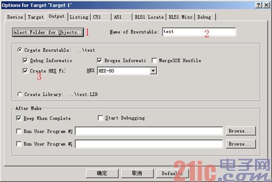
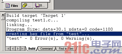
The first MCU C language project has been established. However, in order to allow the compiled program to be written into the 51 chip through the programmer, the compiler must be used to generate a HEX file first. Let's take a look at how to use KEIL uVISION2 to compile and generate a HEX file for burning the chip. The HEX file format is data information arranged by address proposed by Intel. The data width is bytes, and all data is represented by hexadecimal numbers. It is often used to save the target program code of the MCU or other processors. It saves the target code image in the physical program storage area. General programmers support this format. Let's open the first project first, open its directory, find the test.Uv2 file, and you can open the previous project. Then right-click the 1 project folder in Figure 2-1, the project function menu pops up, select Options for Target'Target1', and the project option setting window pops up. Also select the project folder icon first, and the same menu is available in the Project menu at this time. Open the project option window, go to the Output option page as shown in Figure 2-2. In the figure, 1 is to select the path for compilation output, 2 is to set the file name generated by the compilation output, and 3 is to decide whether to create a HEX file. Select it to output the HEX file to the specified path. Have you made your choice? OK, we will recompile it again, and soon the compilation information window will show that the HEX file has been created in the specified path, as shown in Figure 2-3. In this way, we can use the software attached to our programmer to read and burn it to the chip, and then use the experimental board to see the results. As for the various types of programmers or emulators, the specific methods can be found in their manuals, and they will not be discussed here.
(Tips: 1. In the project file tree in 1 in Figure 2-1, select the object first, then click it to rename it, and double-click the file icon to open the file. 2. At the bottom of the Project drop-down menu, there is a list of recently edited files.
The project path is saved here, and the most recently edited project can be quickly opened here. )
Figure 2-1 Project function menu

Figure 2-2 Project Options Window

Figure 2-3 Compile Information Window [page]
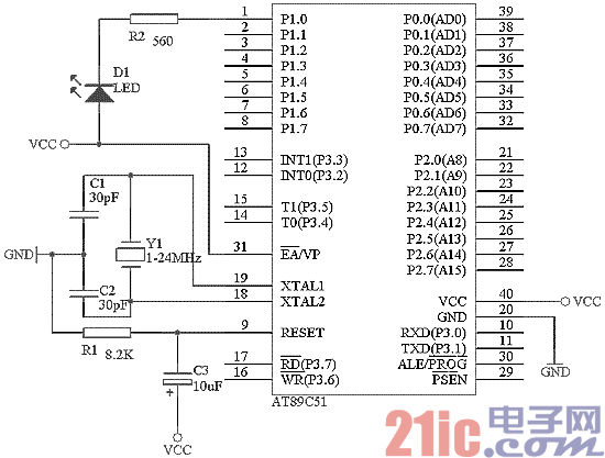
Perhaps you have burned the compiled file to the chip. If you buy or make a learning experiment board with serial port output components, you can connect the serial port to the PC serial port and use the serial port debugging software or Windows HyperTerminal to set the baud rate to 1200, and you can see the words "Hello World!" being output continuously. If you don't have an experiment board yet, let's talk about the AT89c51 minimum system first, and then use an example program to verify whether the minimum system is running. This minimum system is also easy to make for experiments. Figure 2-4 is the minimum system of AT89c51. However, in order to let us see that it is running, a resistor and an LED are added to display its status. The crystal oscillator can be used according to your own situation. Generally, 11.0592MHz or 12MHz is used on the experiment board. The advantage of the former is that it can generate a standard serial port baud rate, while the latter has a machine cycle of 1 microsecond, which is convenient for precise timing. In my own experiments, please note that VCC is +5V. It cannot be higher than this value, otherwise the microcontroller will be damaged. If it is too low, it will not work properly. Pin 31 must be connected to a high level so that we can execute the program in the chip. If it is connected to a low level, the program memory outside the chip will be used. Next, create a new project named OneLED to verify whether the minimized system can work. The program is as follows:
#include
void main(void) //main function name
{
//This is the first comment method
unsigned int a; //define variable a as int type
/* This is the second comment type
*/
do{ //do while loop
for (a=0; a<50000; a++); //This is a loop P1_0 = 0; //Set P1.0 port to low level and turn on the LED for (a=0; a<50000; a++); //This is a loop P1_0 = 1; //Set P1.0 port to high level and turn off the LED
}
while(1);
}

Figure 2-4 AT89c51 Minimized System
Here we will first talk about the comment statements supported by the KEIL C compiler. One is the statement that starts with the "//" symbol. The statements after the symbol are considered comments until there is a carriage return. The other is the comment within the "/*" and "*/" symbols. Comments will not be compiled by the C compiler. A C application should have a main function. The main function can call other functions, but other functions are not allowed to call the main function. No matter where the main function is placed in the program, it is always executed first. Use the knowledge learned above to compile the written OneLED program and burn it into the newly built minimized system. Power on, the LED is not on at first (because all IO ports are set to 1 pins at high level after power-on reset), then delay for a period of time (for (a=0; a<50000; a++) is running), the LED is on, and then delay again, the LED goes out, and then alternately on and off. The first real small experiment is done. If there is no such effect, then you should carefully check the circuit or the steps of compiling and burning.
Previous article:MCU C Language Tutorial: Appendix 1 Extended Keywords of C51 Compiler
Next article:Microcontroller C language tutorial: Use of C51 pointers
Recommended ReadingLatest update time:2024-11-16 20:56


- Popular Resources
- Popular amplifiers
-
 Wireless Sensor Network Technology and Applications (Edited by Mou Si, Yin Hong, and Su Xing)
 -
 Modern Electronic Technology Training Course (Edited by Yao Youfeng)
 -
 Modern arc welding power supply and its control
 -
 Small AC Servo Motor Control Circuit Design (by Masaru Ishijima; translated by Xue Liang and Zhu Jianjun, by Masaru Ishijima, Xue Liang, and Zhu Jianjun)
 Professor at Beihang University, dedicated to promoting microcontrollers and embedded systems for over 20 years.
- Innolux's intelligent steer-by-wire solution makes cars smarter and safer
- 8051 MCU - Parity Check
- How to efficiently balance the sensitivity of tactile sensing interfaces
- What should I do if the servo motor shakes? What causes the servo motor to shake quickly?
- 【Brushless Motor】Analysis of three-phase BLDC motor and sharing of two popular development boards
- Midea Industrial Technology's subsidiaries Clou Electronics and Hekang New Energy jointly appeared at the Munich Battery Energy Storage Exhibition and Solar Energy Exhibition
- Guoxin Sichen | Application of ferroelectric memory PB85RS2MC in power battery management, with a capacity of 2M
- Analysis of common faults of frequency converter
- In a head-on competition with Qualcomm, what kind of cockpit products has Intel come up with?
- Dalian Rongke's all-vanadium liquid flow battery energy storage equipment industrialization project has entered the sprint stage before production
- Allegro MicroSystems Introduces Advanced Magnetic and Inductive Position Sensing Solutions at Electronica 2024
- Car key in the left hand, liveness detection radar in the right hand, UWB is imperative for cars!
- After a decade of rapid development, domestic CIS has entered the market
- Aegis Dagger Battery + Thor EM-i Super Hybrid, Geely New Energy has thrown out two "king bombs"
- A brief discussion on functional safety - fault, error, and failure
- In the smart car 2.0 cycle, these core industry chains are facing major opportunities!
- The United States and Japan are developing new batteries. CATL faces challenges? How should China's new energy battery industry respond?
- Murata launches high-precision 6-axis inertial sensor for automobiles
- Ford patents pre-charge alarm to help save costs and respond to emergencies
- New real-time microcontroller system from Texas Instruments enables smarter processing in automotive and industrial applications
- The shielding layer of the inductor in the DC-DC circuit is broken, causing the hot-swap circuit to have no output.
- Test solution download: R&SCMA180 - ideal test tool for analog and digital radio intercoms CMA80
- A complete list of new domestic AD/DA and other chips,
- How to use the 5V output of a microcontroller to drive a 24V solenoid valve?
- RLC analog circuit design
- Verilog implements full parallel comparison algorithm.zip
- The serial port cannot be interrupted, but the register settings are correct when emulating.
- msp430 PWM period calculation
- Latest feeling: There are more beauties after wearing masks
- What are the Bluetooth output power, receiving sensitivity, resolution, TX transmission current, RX receiving current, and data rate?

 Wireless Sensor Network Technology and Applications (Edited by Mou Si, Yin Hong, and Su Xing)


 京公网安备 11010802033920号