1 Introduction
Sinusoidal pulse width modulation (SPWM) technology has been widely used in the fields of AC speed regulation, DC power transmission, variable frequency power supply, etc. In order to improve the control effect of the whole system, high-performance SPWM pulse forming technology has been a problem that people have been exploring. Using hardware circuits such as analog circuits and digital circuits to generate SPWM waveforms is a feasible method, but this implementation method has complex control circuits, poor anti-interference ability, and difficult real-time adjustment. In recent years, people have proposed digital control methods for SPWM waveforms using microcontrollers such as single-chip microcomputers and DSPs [1][2]. Since the microcontroller integrates many control circuits, such as timers, PWM circuits, programmable counter arrays, etc., this method of implementing SPWM has the advantages of simple control circuits, fast running speed, high control accuracy, and strong anti-interference ability. This paper introduces a method of using C8051 single-chip microcomputer to realize variable output frequency SPWM waveforms, and applies the unipolar SPWM wave generated by C8051F040 to a single-phase frequency adjustable inverter power supply. The experimental results confirm the feasibility and effectiveness of using C8051 to realize SPWM waveforms.
2 SPWM Technology Principle
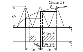
The basic principle of SPWM technology is to compare a triangular wave carrier with a sine wave to obtain a pulse sequence whose width changes according to the sine law, and use them to drive the switching conversion of the inverter switch tube. There are three methods to realize SPWM waveform by microcontroller: table method, real-time calculation method and real-time calculation method, but the first two do not have real-time processing capabilities [2]. The real-time calculation method requires a mathematical model. One of the more commonly used is the sampling type SPWM method, which is divided into natural sampling method, symmetrical regular sampling method and asymmetrical regular sampling method. This paper adopts the symmetrical regular sampling method, that is, the sampled sine wave (actually a step wave) is intersected with the triangular wave, and the pulse width is obtained from the intersection point. Figure 1 is a typical unipolar symmetrical regular sampling method. It only samples the sine modulated wave at the peak moment of the triangular wave and holds the sampled value. The held value and the intersection point of the triangular wave are taken as the pulse width time. In the figure, Ts is the period of the triangular wave, which is also the sampling period; Ur is the height of the triangular wave, and the sine wave is Ucsinωt. According to the triangle similarity relationship, we get

so

Among them, M=Uc/Ur is the modulation ratio, and t is the time of the sampling point (here is the vertex sampling). Then the pulse width is

The sampling point time t is only related to the carrier ratio N. For the case of Figure 1, t = kTS + θ, where k = 0, 1, 2, ..., N-1, θ = 180/N degrees.

Figure 1 Symmetrical regular sampling method
In the case of symmetrical regular sampling, as long as the sampling point time t is known, the pulse width tpw and time interval toff within this sampling period can be determined, thereby calculating the width of the high and low pulses of the SPWM waveform.
3 Principle and algorithm of C8051 to realize SPWM waveform
3.1 Introduction to PCA of C8051F Series MCU
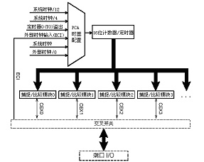
The C8051F series microcontrollers all have a programmable counter array PCA. Taking C8051F040 as an example, the PCA contains 1 dedicated 16-bit counter/timer and 6 16-bit capture/compare modules, which can output 6 PWM waveforms. As shown in Figure 2, there are multiple options for the time base signal of the 16-bit PCA dedicated counter/timer, which can be achieved by configuring the special function registers (SFR) of the relevant system controller. Each capture/compare module has its own I/O line CEXn, and the I/O line of each module can be connected to the port I/O by configuring the cross switch register (XBR0); each module can be configured to work independently, with four working modes: edge-triggered capture, software timer, high-speed output, and so on.

Figure 2 PCA principle block diagram [page]
Output or pulse width modulator. In this article, the variable frequency SPWM waveform is generated by using the high-speed output working mode of the capture/compare module. The principle is as follows:
When the PCA's 16-bit counter/timer PCA0H (high 8 bits) and PCA0L (low 8 bits) match the 16-bit capture/compare module registers PCA0CPHn (high 8 bits) and PCA0CPLn (low 8 bits), the logic level on the module's CEXn pin will change and generate an interrupt request, setting the corresponding CCFn bit in the control register PCA0CN. When the CCF interrupt is enabled, the CPU will turn to the CCF interrupt service routine. If the I/O line CEXn of the corresponding module is connected to the port I/O, the output level of the corresponding port of the microcontroller will change, which can achieve high and low level output of PWM pulses. Setting the TOGn, MATn, ECOMn and ECCFn bits in the PCA0CPMn register will allow high-speed output mode and CCF interrupts [3].
3.2 SPWM waveform generation method
The basic principle of using the PCA counter of C8051 to generate SPWM waveform is: under high-speed output and allowing CCF interrupt mode, the pulse width of the pre-calculated SPWM waveform is continuously added to the capture/compare module register PCA0CPn (high 8-bit PCA0CPHn and low 8-bit PCA0CPLn) in the CCF interrupt service program. In this way, when the capture/compare module register and the counter/timer match, the corresponding SPWM waveform with alternating high and low levels is obtained.
In Figure 3, l0, h0, l1, h1…lmax, hmax are the high and low pulse widths of a unipolar SPWM waveform calculated by the software in real time, where l0 = l0'+T/2. Since the output is a variable frequency SPWM waveform, that is, the modulation wave frequency is variable, different carrier ratios N are set in different frequency bands, so the value of max is only relatively fixed.

Figure 3 SPWM waveform diagram
If the capture/compare module 0 is selected to output this SPWM, first l0' is loaded into the 16-bit capture/compare register PCA0CP0, and the 16-bit counter/timer PCA0H and PCA0L are cleared, and then the PCA counter is started; when the value of the capture/compare register is equal to the value of the counter/timer, the CEX0 pin will jump from the original low level to the high level, and a CCF interrupt will be generated; in the CCF interrupt program, h0 is accumulated to PCA0CP0; during the interrupt process, the value of the counter is continuously increased, and when its value is equal to the value of the changed capture/compare register, the CEX0 pin will jump from the original high level to the low level, and a CCF interrupt will be generated; then l1 is accumulated to PCA0CP0 during the interrupt process. In this way, the CEX0 pin will continuously generate alternating high and low levels, so that an accurate SPWM waveform can be obtained on the corresponding port I/O.
3.3 PCA Register Settings
In order to implement the above SPWM waveform generation method, it is necessary to set the special function registers related to PCA operation. The details are as follows:
1) Set the mode selection register PCA0MD.
2) Initialize the capture/compare registers PCA0CPHn (high byte) and PCA0CPLn (low byte).
3) Set the capture/compare mode register PCA0CPMn.
4) Initialize the counter/timer PCA0H (high byte) and PCA0L (low byte).
5) Set the control register PCA0CN.
3.4 Program Flow
The main program flow is shown in Figure 4. After the system is initialized, the output frequency is first set through the keyboard, and then the SPWM pulse width calculation program is entered. The modulation ratio N is selected according to the set frequency, the pulse width is calculated, and the max is determined. In the SPWM output program, the PCA special function register is set and the counter is started to start outputting the SPWM waveform.
In the interrupt service program, first determine the capture/compare module where the match occurs based on the value of CCFn, and then determine whether to add the high-level pulse width value or the low-level pulse width value of the SPWM waveform to the capture/compare module register based on the level state of the module's CEX pin; at the same time, determine the end of an SPWM cycle and the beginning of the next cycle based on whether the pulse width data pointer is equal to max, so as to correctly load the corresponding data. When the carrier ratio N changes, the value of max will change.

Figure 4 Program flow chart [page]
One thing that should be noted is that the CCFn bit and CF bit (counter/timer overflow flag) are set by hardware, but cannot be automatically cleared to 0 by hardware and must be cleared to 0 by software in the interrupt program.
4 Analysis of the minimum pulse problem
Due to hardware reasons, no microcontroller can output pulses with infinitely small widths, which means that narrow pulses less than a certain width in the ideal SPWM pulse sequence cannot be output normally, which is the minimum pulse problem.
For the C8051 microcontroller, the minimum pulse that its PCA can output depends on the execution time of its interrupt service program, so its minimum pulse problem cannot be ignored. The specific methods to solve this problem are: ① Use assembly language to write the interrupt service subroutine and apply the most concise and time-saving instructions to reduce the width of the minimum pulse; ② When calculating the SPWM wave pulse width, correct the pulses whose width is less than the minimum width that the PCA can output so that their width is the width of the minimum pulse; ③ Limit the modulation ratio M so that the SPWM pulse sequence does not contain too many small pulses.
5 Experimental Results
The main circuit of the experiment is a single-phase full-bridge inverter circuit. The main switch tube uses IGBT, which outputs 100V, 50-400Hz adjustable frequency AC voltage. The single-chip microcomputer outputs two complementary (with a certain dead time) unipolar SPWM waves to control the inverter power supply.
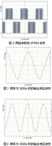
In the experiment, the minimum pulse problem of the output SPWM wave was dealt with, and the interrupt service subroutine was programmed in assembly language, so that the width of the minimum pulse in the SPWM waveform reached 3us, which basically reached the minimum switching period of the IGBT used in the experiment. Figure 4 shows the experimental waveforms of two unipolar SPWM waves, and Figures 5 and 6 show the output voltage experimental waveforms at frequencies of 200Hz and 300Hz respectively:

It can be seen from the experimental waveform that the control effect of the SPWM wave generated by C8051 is better, and the frequency of the output voltage can be adjusted accurately and in real time.
6 Conclusion
Using C8051 single-chip microcomputer to generate SPWM waveform is a simple and easy method, which has the characteristics of high calculation accuracy and strong real-time adjustment. At the same time, by changing the method of calculating the pulse width of SPWM wave, bipolar SPWM waveform can be easily realized. Therefore, this method is suitable for occasions with different requirements on the polarity, number of paths and frequency of the output SPWM waveform.
References
[1] Li Zicheng et al. Research on SPWM wave formation based on 87C196MC [J]. High Voltage Technology, 2004 (12): 10-12
[2] Lu Huifen. A method for generating SPWM control waveform based on DSP [J]. Mechanical and Electrical Engineering, 2002 (5): 30-34
[3] Li Gang, Lin Ling. High-performance, high-speed microcontroller compatible with 8051 - C8051Fxxx. Beijing: Beijing University of Aeronautics and Astronautics Press, 2002
Previous article:Design of Real-time Clock X1226 Controlled by Single Chip Microcomputer
Next article:Design of three-phase bridge controllable trigger circuit based on ATMEL89S52 single chip microcomputer
Recommended ReadingLatest update time:2024-11-16 16:40

- Popular Resources
- Popular amplifiers
-
 MCU C language programming and Proteus simulation technology (Xu Aijun)
 -
 Principles and Applications of Single Chip Microcomputers 3rd Edition (Zhang Yigang)
 -
 Principles and Applications of Single Chip Microcomputers and C51 Programming (3rd Edition) (Xie Weicheng, Yang Jiaguo)
 -
 MCU Principles and Interface Technology C51 Programming (Edited by Zhang Yigang)
 Professor at Beihang University, dedicated to promoting microcontrollers and embedded systems for over 20 years.
- Innolux's intelligent steer-by-wire solution makes cars smarter and safer
- 8051 MCU - Parity Check
- How to efficiently balance the sensitivity of tactile sensing interfaces
- What should I do if the servo motor shakes? What causes the servo motor to shake quickly?
- 【Brushless Motor】Analysis of three-phase BLDC motor and sharing of two popular development boards
- Midea Industrial Technology's subsidiaries Clou Electronics and Hekang New Energy jointly appeared at the Munich Battery Energy Storage Exhibition and Solar Energy Exhibition
- Guoxin Sichen | Application of ferroelectric memory PB85RS2MC in power battery management, with a capacity of 2M
- Analysis of common faults of frequency converter
- In a head-on competition with Qualcomm, what kind of cockpit products has Intel come up with?
- Dalian Rongke's all-vanadium liquid flow battery energy storage equipment industrialization project has entered the sprint stage before production
- Allegro MicroSystems Introduces Advanced Magnetic and Inductive Position Sensing Solutions at Electronica 2024
- Car key in the left hand, liveness detection radar in the right hand, UWB is imperative for cars!
- After a decade of rapid development, domestic CIS has entered the market
- Aegis Dagger Battery + Thor EM-i Super Hybrid, Geely New Energy has thrown out two "king bombs"
- A brief discussion on functional safety - fault, error, and failure
- In the smart car 2.0 cycle, these core industry chains are facing major opportunities!
- The United States and Japan are developing new batteries. CATL faces challenges? How should China's new energy battery industry respond?
- Murata launches high-precision 6-axis inertial sensor for automobiles
- Ford patents pre-charge alarm to help save costs and respond to emergencies
- New real-time microcontroller system from Texas Instruments enables smarter processing in automotive and industrial applications
- How are Hall Effect Switches Used to Measure Car Speed?
- [GD32E231 Work Submission] Quartz Accelerometer Acquisition
- Combining wired and wireless connections to build an intelligent cloud gateway
- ORCAD Network Numbers and Buses
- 5G is coming, 4G speed is slowing down? Learn about load balancing link aggregators
- TE Welfare Month|Rewarded surveys, technical tips, limited-time discounts
- I want to draw the shells of some small products myself and then 3D print them. Which software is easier to use?
- Practical Electronic Components and Circuit Basics (2nd Edition)
- WiFi wireless changes: Goodbye 802.11, WiFi 4/5/6 is coming
- DIY Smart Timer

 MCU C language programming and Proteus simulation technology (Xu Aijun)


 京公网安备 11010802033920号