With the process of urbanization, the distance of people's lives is constantly expanding. The popularity of electric vehicles that replace fuel vehicles and bicycles has greatly improved the utilization efficiency of power resources and promoted the healthy development of the national economy. Electric bicycles are powered by electricity, do not produce pollution during riding, and do not damage the air quality. From the perspective of improving people's travel methods, protecting the environment, and economic conditions, electric bicycles have broad development space at present and in the future. The DC motors used in electric bicycles are divided into two types: brushed motors and brushless motors. Among them, the control of brushed motors is relatively simple. However, its easily worn brushes bring disadvantages such as relatively large maintenance workload and relatively short service life. The brushless DC motor itself has no easily worn parts, long motor life, and small maintenance workload. However, the brushless DC motor works on the principle of electronic commutation, and its control process is much more complicated than that of the brushed motor, so the requirements for the quality of the controller are also much higher.
At present, the brushless DC motors used in electric bicycles are all three-phase motors, with two electrical angles of 60° and 120°. Most of the motor poles are 18 poles, and there are also 16 poles and 20 poles. The controller controls the opening or closing of the corresponding power drive tube according to the motor electrode position fed back by the Hall effect, generates a rotating magnetic field in the stator, and drives the motor rotor to rotate.
In order to determine whether the brushless controller can operate normally, that is, to detect whether the handlebar and brake functions are normal, determine whether the angle of the controller is 60° or 120°, and determine the correspondence between the winding A, B, C phases and the position signals a, b, c, and correctly connect the controller to the motor. Now many detection instruments use analog circuits, which makes the results not very accurate, and the required circuits are also very complex and costly. The design uses the STCl2C5410AD microcontroller as the control chip, which greatly simplifies the hardware circuit and is implemented by software programming.
l Introduction to the brushless motor controller for electric vehicles
The controller consists of peripheral devices and a main chip (or microcontroller). Peripheral devices are some functional devices, such as execution, sampling, etc. They are resistors, sensors, bridge switch circuits, and devices that assist single-chip computers or special integrated circuits to complete the control process; single-chip computers are also called microcontrollers, which are integrated with memory, decoders that convert signal languages, sawtooth wave generators, pulse width modulation functional circuits, and drive circuits that can turn on or off the power tube of the switch circuit, and control the motor speed by controlling the conduction time of the power tube through square waves, and input and output ports. This is the intelligent controller of the electric bicycle. The
design quality, characteristics, functions of the microprocessor used, power switch device circuits, and layout of peripheral devices of the controller are directly related to the performance and operating status of the whole vehicle, and also affect the performance and efficiency of the controller itself. Controllers of different qualities, used on the same vehicle, equipped with the same set of batteries in the same charge and discharge state, sometimes show large differences in driving range.
At present, the circuit principles of the controllers used in electric bicycles are basically the same or similar. Most brushed and brushless DC motors use pulse width modulation (PWM) control method for speed regulation, but the differences are in the selection of drive circuits, integrated circuits, switching circuit power transistors and some related functions. The differences in components and circuits constitute the difference in controller performance.
2 System hardware circuit design
In order to determine whether the brushless controller is normal, measure whether the output signals of each part of the controller meet the standards, and be able to receive signals from the motor, handle, and brake, and determine whether the controller can achieve the functions it needs to achieve, the system must detect whether the controller's handle and brake have a stable 5 V voltage output, determine the angle of the controller, and determine whether the phase sequence of the Hall control line and the corresponding motor power supply phase sequence are consistent. Only when the position sensor signal and windings A, B, and C are correctly connected can the motor operate normally. Figure 1 is the overall circuit design schematic diagram. The system uses the STCl2C5410AD microcontroller as the main control chip. The STCl2C5410AD series of MCUs are single clock/machine cycle (1T) MCUs produced by Hongjing Technology. They are a new generation of 8051 MCUs with high speed, low power consumption and super anti-interference. The instruction code is fully compatible with the traditional 8051, but the speed is 8 to 12 times faster. It has an internal integrated MAX810 dedicated reset circuit, 4-channel PWM, and 8-channel high-speed 10-bit A/D conversion, which is specially designed for motor control in strong interference situations.

2.1 Bridge rectifier circuit
Because the controller needs direct current to work, a rectifier circuit is needed. The system uses a single-phase bridge rectifier circuit. This circuit has the advantages of a full-wave rectifier circuit as long as the four diode ports are connected into a "bridge" structure.
2.2 Detection of brake and throttle signals
The change in the high and low potential of the brake signal is the basis for the controller to identify whether the electric vehicle is in a braking state, and thus determine whether the controller supplies power to the motor. As long as the output ends of the brake and throttle signals are connected to the A/D conversion terminals P16 and P17 of the STCl2C5410AD microcontroller, it is possible to detect whether the output is normal. [page]
2.3 Judgment of controller angle and phase sequence
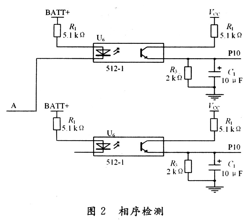
As shown in Figure 2, first determine the output of winding voltage A, connect two optical couplers to the final stage of the controller, and connect them in parallel with the upper and lower tubes of A. When the upper tube of A is turned on, A outputs a high voltage to turn on the lower optical coupler. Thus, a voltage value is output and sent to the single-chip microcomputer through the A/D conversion terminal P11 port of the STCl2C5410AD single-chip microcomputer; when the lower tube of A is turned on, A outputs a low voltage to turn on the upper optical coupler, thereby outputting a voltage value and sending it to the single-chip microcomputer through the A/D conversion terminal P10 port of the STCl2C5410AD single-chip microcomputer. B and C use the same connection method as above. There is no direct output when outputting, but it is output after being isolated by the optical coupler. The reasons are as follows: the signal of the optical coupler is transmitted unidirectionally, the input and output ends are completely electrically isolated, the output signal has no effect on the input end, it has strong anti-interference ability, stable operation, no contacts, long service life, and high transmission efficiency.

3 System software design
3.1 Overall design flow chart
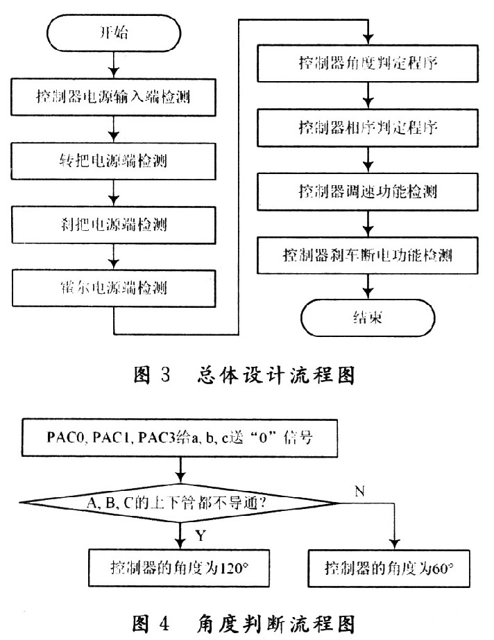
The overall design flow chart is shown in Figure 3.

Measure the impedance of the controller input terminal. When it is greater than 10 Ω, it is normal. Otherwise, the power input terminal is short-circuited. The detection of the turning handle, brake handle, and Hall power supply terminal must ensure that the output voltage is greater than 4.5 V. The judgment of the controller angle and phase sequence is judged and detected according to the brushless truth table. The following is only an example of the controller angle judgment.
3.2 Controller Angle Judgment Program Design
It can be seen from Table 1 that when a, b, and c are all "0" and the controller angle is 120°, the upper and lower tubes of A, B, and C are not turned on; when the controller is 60°, the upper tube of A and the lower tube of B are turned on. In this way, the angle of the controller can be judged according to the output signals of A, B, and C when a, b, and c are all "0". The flow chart is shown in Figure 4.

4 Conclusion
The system design uses STCl2C5410AD single-chip microcomputer as the control chip. The circuit is simple and the measurement is accurate. It meets the various requirements of electric vehicle brushless motor controller detection. It can detect whether the controller is connected to the handlebar and brake handle. It can judge whether the controller angle, Hall control phase sequence and the corresponding motor power phase sequence are consistent. It is hoped that this design will be better improved and perfected in future applications.
Previous article:Design and implementation of educational robot based on STC12C5A60S2
Next article:Design of controllable electric wrench controller based on STC12C5A60S2
- Popular Resources
- Popular amplifiers
 Professor at Beihang University, dedicated to promoting microcontrollers and embedded systems for over 20 years.
- Innolux's intelligent steer-by-wire solution makes cars smarter and safer
- 8051 MCU - Parity Check
- How to efficiently balance the sensitivity of tactile sensing interfaces
- What should I do if the servo motor shakes? What causes the servo motor to shake quickly?
- 【Brushless Motor】Analysis of three-phase BLDC motor and sharing of two popular development boards
- Midea Industrial Technology's subsidiaries Clou Electronics and Hekang New Energy jointly appeared at the Munich Battery Energy Storage Exhibition and Solar Energy Exhibition
- Guoxin Sichen | Application of ferroelectric memory PB85RS2MC in power battery management, with a capacity of 2M
- Analysis of common faults of frequency converter
- In a head-on competition with Qualcomm, what kind of cockpit products has Intel come up with?
- Dalian Rongke's all-vanadium liquid flow battery energy storage equipment industrialization project has entered the sprint stage before production
- Allegro MicroSystems Introduces Advanced Magnetic and Inductive Position Sensing Solutions at Electronica 2024
- Car key in the left hand, liveness detection radar in the right hand, UWB is imperative for cars!
- After a decade of rapid development, domestic CIS has entered the market
- Aegis Dagger Battery + Thor EM-i Super Hybrid, Geely New Energy has thrown out two "king bombs"
- A brief discussion on functional safety - fault, error, and failure
- In the smart car 2.0 cycle, these core industry chains are facing major opportunities!
- The United States and Japan are developing new batteries. CATL faces challenges? How should China's new energy battery industry respond?
- Murata launches high-precision 6-axis inertial sensor for automobiles
- Ford patents pre-charge alarm to help save costs and respond to emergencies
- New real-time microcontroller system from Texas Instruments enables smarter processing in automotive and industrial applications
- Seek help from testing and packaging partners
- Summary: BearPi-Hongmeng-BearPi-HM Nano Review Summary
- "In-depth understanding of BootLoader", introducing the development theory, process and examples of BootLoader
- Weekly review information is here~
- Share an easy-to-understand msp430 microcontroller learning tutorial
- Simulation of a Microstrip Patch Antenna for 2.4 GHz Applications with Radiat...
- Analysis of DSP2407's frame pointer (FP) and stack pointer (SP)
- msp430 MCU rc522 radio frequency program and circuit diagram
- EEWORLD University Hall----FPGA Design Skills and Specifications
- C8051F040 has a CAN interrupt, how to determine which mailbox caused the interrupt

 Electric Vehicle Wireless Battery Management Revolution Has Begun and the ROI Potential Is Huge


 京公网安备 11010802033920号