|
Topics in previous national electronic design competitions can be divided into power supply, signal source, radio, amplifier, instrumentation, data acquisition and processing, and automatic control. In the 2005 National College Student Electronic Design Competition, suspended object control The system is a typical automatic control competition question. This article focuses on introducing a control system solution based on dual microcontrollers for suspended objects to move along any curve marked on the board.
1 System design requirements and design ideas
The question requires controlling the movement of objects along any curve marked on the board, as shown in Figure 1. The curve is marked on site during the test. The line width is 1.5cm~1.8cm, the total length is about 50cm, and the color is black; the first part of the curve is continuous and about 30cm long; the latter part is two intermittent line segments with a total length of about 20cm. , the discontinuous distance is not greater than 1cm; the movement along the continuous curve is limited to be completed within 200s, and the movement along the discontinuous curve is limited to be completed within 300s.
|
According to the requirements of the topic, the system mainly implements functions such as black line and breakpoint detection, and motion control of suspended objects. In order to illustrate that the system can realize tracking in any curve and in any direction, a circular trajectory is used as the tracking object. The tracking principle is shown in Figure 2.
The coordinates of the initial point A of the suspended object are input through the keyboard. An infrared probe is installed at the initial moment, and the rocker arm controlled by a micro stepper motor is in a horizontal position. After the system is started, the micro stepper motor drives the rocker arm to rotate clockwise, with a maximum rotation angle of 180°. There will be an intersection point B between the motion trajectory of the infrared probe and the black arc, and the angle of rotation of the stepper motor will be recorded. Through the coordinates of the starting point A of the system and the angle of rotation of the stepper motor, the coordinates of the next point B under motion control can be obtained. After obtaining the coordinates of point B, control the suspended object to move in a straight line toward that point, and at the same time, the rocker arm rotates 90° counterclockwise to ensure that the next detected intersection point is within its 180° search range. If the rocker arm rotates 180° and there is still no intersection, the curve is considered to have a breakpoint here, and the system controls the hanging object to continue moving one step in the original direction and scan again to find the position of the next detection point. If the suspended object deviates from the trajectory, such as the position of point C in Figure 2, the system can also automatically return the suspended object to the trajectory point through the detection of the next point. Therefore, this method can effectively correct the trajectory deviation and achieve tracking control capabilities.
2 System scheme design
The basic scheme block diagram of the suspended object motion control system is shown in Figure 3. The system mainly consists of a control module, a black line detection module and a communication module. Among them, the control module is composed of ATmega128L microcontroller minimum system 1, keyboard input circuit, liquid crystal display circuit and stepper motor drive circuit; the detection module is composed of ATmega128L microcontroller minimum system 2, infrared reflection circuit and micro-stepper motor drive circuit.
The microcontroller system in the black line detection module controls the micro stepper motor to drive the rocker arm equipped with an infrared probe to swing. It detects the black line on the board and obtains the rotation angle of the micro stepper motor. After the angle data is encoded, it is sent to the control module microcontroller system through the wireless transmission module. After the single-chip computer system in the control module receives the angle data. Perform data verification. If the data is accurate, the suspended object is controlled to move a fixed distance from the current coordinates along the rotation angle by controlling the stepper motor drive circuit, and then the next round of detection commands are sent to the detection module; if the data transmission is incorrect, a data reset is sent to the detection module. Send a command and wait for the next round of angle data reception.
3 Hardware design
3.1 ATmega128L microcontroller is the smallest system
microcontroller. It is the core of the entire suspended object motion control system and controls all circuits of the system. This system uses Atmel's ATmega128L microcontroller, which has the following characteristics:
① The working voltage is 2.7 ~ 5.5 V. It can withstand a wide range of voltage fluctuations and can effectively overcome the power supply voltage caused by the micro stepper motor in the module. The interference caused by instability enables the system to operate normally within a wide range of levels.
②The film is rich in resources. ATmega128L has large memory capacity, including 128 KB Flash, 4 KB E2PROM and 4 KB RAM, which can meet the system's complex calculations and a certain amount of data storage requirements; 53 I/O ports can meet the system's multi-sensor input and multi-control output Port requirements; I/O ports have the characteristics of large current output and strong driving ability; built-in watchdog improves the system's anti-interference ability.
③Online programming is available to facilitate system testing.
3.2 Infrared reflection circuit
uses an infrared reflection sensor with pulse modulation function to detect the black line trajectory. The circuit is shown in Figure 4. The phase-locked audio decoder LM567 in the circuit serves as both the signal generating circuit of the infrared transmitting part and the detection circuit of the receiving part. Only when the frequency of the detected input signal is the same as its own phase-locked center frequency, the output terminal is low level. This circuit can easily filter out external interference, and has strong stability and anti-interference ability. At the same time, it can adjust different center frequencies of the decoder, so that multiple infrared sensors can be used on the same device without interfering with each other.
3.3 Stepper motor drive circuit
The motor in the control system uses the PX245-01A stepper motor from VEXTA Company, with a rated voltage of 4 V, a quiescent current of 1.2 A, and a step angle of 1.8°. The drive circuit of the stepper motor is shown in Figure 5. The Darlington tube acts as a power amplifier to enhance the driving capability of the stepper motor. Optocouplers are used in the circuit to isolate control and drive signals, effectively reducing the impact of external interference on the system and improving system reliability.
3.4 Input and display circuit
This design uses a 4×4 matrix scanning non-coding keyboard to realize the initial point coordinate input and control command input of the suspended object. System control parameters and suspended object movement trajectories can be displayed on the dot matrix LCD12864.
3.5 Wireless communication module
It is not planned to use wireless Modem RF2000 to realize the two-way transmission of data and commands between the system detection module and the system control module. The circuit is shown in Figure 6. RF2000 uses Nordic's nRF401 chip and adopts the FSK modulation method with strong anti-interference ability. The transceiver method can be controlled through the TXEN pin. During wireless transmission, it is susceptible to electromagnetic interference caused by external electromagnetic waves and the rotation of stepper motors, resulting in a high bit error rate. In order to ensure the reliability of data transmission, this design enhances the system's error correction capability through coding. Data or commands are encoded in 8-bit data, that is, one byte, and divided into high-order 4 bits and low-order 4 bits for wireless transmission. Take the transmission of lower 4-bit data as an example. The definition format of the data structure sent is as follows:
The transmission is subject to two levels of error checking. DO~D3 are the lower 4-bit data of the transmitted data, D4~D6 are set to 0, and D7 is the CRC check of the lower 4-bit data.
4.
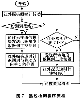
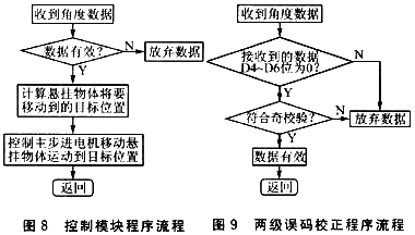
In the software design system, the hanging object tracking adopts a dual microcontroller control scheme. The black line detection module and the hanging object control module each have a single-chip microcomputer system. Collaborative control is achieved through the communication module to complete the hanging object tracking task. The black line detection program flow and the control module program flow are shown in Figures 7 and 8 respectively, and the communication error correction process is shown in Figure 9.
  ? |
5 Test methods and results
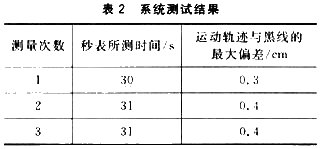
In order to allow the suspended object to move along any curve, this system uses circular curves as the test approach. The circumferential curve contains turning points in four directions and is representative to a certain extent. The circumferential diameter is 30 cm and the circumferential length is about 94 cm, which is larger than the 80 cm required by the design. The test results are listed in Table 2.
Conclusion
This design uses two ATmega128L microcontrollers as the core of black line detection and suspended object motion control respectively. It imitates the radar scanning and tracking system and uses micro stepper motors and infrared sensors to scan and track black lines to achieve continuous black lines and interruptions of the system. Continue to trace the black line. The two cores of black line detection and motion control realize mutual communication of detection data and control commands through wireless data transmission modules. The test results show that this system has high control accuracy, short response time, and strong disconnection tracing capabilities. |


 Operational Amplifier Practical Reference Handbook (Edited by Liu Changsheng, Zhao Mingying, Liu Xu, etc.)
 A Complete Illustrated Guide to Operational Amplifier Applications (Written by Wang Zhenhong)
 Design of isolated error amplifier chip for switching power supply_Zhang Rui
 DAM medium wave transmitter high frequency power amplifier module test platform_Tian Tian
 Professor at Beihang University, dedicated to promoting microcontrollers and embedded systems for over 20 years.


 ?
?
 Operational Amplifier Practical Reference Handbook (Edited by Liu Changsheng, Zhao Mingying, Liu Xu, etc.)


 京公网安备 11010802033920号