In the management of goods in the warehouse, it is necessary to monitor environmental parameters such as temperature and humidity to ensure the safety of the warehouse. As the area of the warehouse gradually expands, a monitoring system with strong transmission capacity and long communication distance is needed to effectively supervise the goods in the warehouse.
CAN (Controller Area Network) bus technology has the advantages of advanced multi-master network structure, long communication distance, low price, high reliability, large system capacity, easy installation, low maintenance cost, high cost performance, etc. It is particularly suitable for monitoring large warehouses with large storage areas and scattered warehouses.
2 System Hardware Design
This system adopts a distributed monitoring network, which is mainly divided into two parts: the upper computer and the lower computer. The upper computer hardware includes a CAN communication adapter and an upper monitoring management computer; the lower computer consists of a CAN node, a field sensor group, and a temperature and humidity parameter controller, as shown in Figure 1.
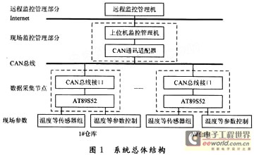
Its working principle is that the lower computer node sends the message containing address, temperature, humidity and other data to the CAN bus at a certain time interval. The bus determines through its own arbitration that the data with the highest priority is placed on the bus first, and then automatically arbitrates and sends the messages with relatively low priority to the CAN bus in turn. Since the information access of the CAN bus utilizes the broadcast access working mode, the message can be sent to the idle bus by any node at any time. Each CAN bus node receives the message information appearing on the bus. Through the message filtering and address setting of each node, the upper computer CAN node can realize the reception of the uploaded message. After receiving the message information, the upper computer uses the KingView software to realize real-time monitoring and recording of parameters such as warehouse temperature. At the same time, the upper computer can send control information to the CAN bus at any time through the warehouse human-machine interface, and the CAN bus node with matching address can receive the information. In this way, feedback control of parameters such as warehouse temperature can be realized.
2.1 Hardware design of the host computer system
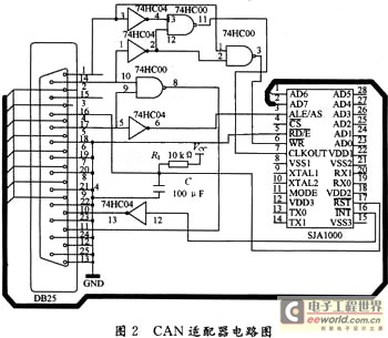
The CAN communication adapter is responsible for data forwarding between the host computer and the CAN node, and realizes the communication between the host computer and the slave computer. The key to realizing the communication between the PC and the SJA1000 using the EPP parallel port is to realize the read and write timing of the SJA1000. There are two ways to achieve this: software generates the read and write timing circuit and hardware generates the read and write timing circuit. This system uses hardware to generate the read and write timing circuit, and generates the SJA1000 handshake and other signals through the time delay of the logic gate. The designed circuit is shown in Figure 2.
2.2 Hardware design of the lower computer system
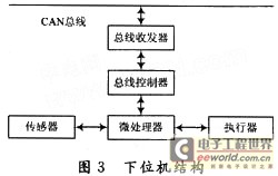
The lower computer includes CAN nodes, field sensor groups and temperature and humidity parameter controllers. The CAN nodes are mainly used to complete the configuration of CAN bus signals and CAN network communications. The field sensor group and parameter controller are mainly used to complete real-time monitoring of the temperature and humidity of each test point in the warehouse with the CAN nodes. They are also responsible for receiving commands from the upper management computer, transmitting data and feedback control according to the requirements of the upper management computer. The structure of the lower computer is shown in Figure 3.
2.2.1 CAN Node
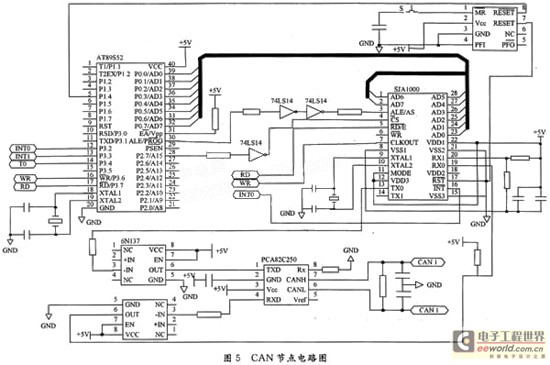
CAN node devices mainly include: microprocessor AT89S52 single-chip microcomputer, CAN controller SJA1000 and CAN bus transceiver PCA82C250.
(1) CAN controller SJA1000
The working mode of SJA1000 is selected by the CAN mode bit in its internal clock divider register CDR. The default mode during hardware reset is BasicCAN working mode. SJA1000 is equivalent to a storage image I/O device relative to the microcontroller. Its address field consists of a control segment and an information buffer segment. During the downloading initialization, the controller can be programmed to set the communication parameters. The communication on the CAN bus can be controlled by the microcontroller through this segment.
Some of the SJA1000 internal registers are only writable, while others are both readable and writable. Before the system works properly, the microcontroller needs to initialize some registers to ensure that the various parts of the system can exchange data correctly. The contents of the CAN controller are all written by the microcontroller, and its read and write timing is shown in Figure 4.
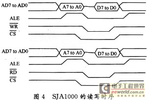
From the read/write timing diagram, the microcontroller operates SJA1000, because SJA1000 can store data address information. The field data acquisition and control layer is responsible for collecting data from the field and sending it to the bus in the format of CAN protocol, and performing real-time control and monitoring of field equipment as needed. After the system is powered on, the microprocessor first initializes itself and SJA1000, and transmits it to the CAN bus or directly displays and controls it on the field; the information from the CAN bus is interrupted. Every time the system receives a frame of information, an interrupt is generated, which triggers the microprocessor to enter an interrupt, read the frame information in the interrupt service program and transmit it to the field.
(2) CAN transceiver PCA82C250
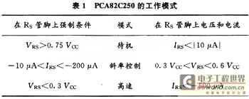
PCA82C250 is a CAN transceiver, which is the interface between the CAN controller and the physical bus. It provides the ability to drive and send the bus, the differential sending ability of the CAN controller, and the differential receiving ability of the CAN controller. It has strong ability to resist instantaneous interference and protect the bus, and has three different working modes: high speed, slope control, and standby. The power failure of a node on the bus will not affect the bus. High-speed applications can reach 1 Mb/s within 40 m, and up to 110 nodes can be connected. Pin 8 (RS) allows PCA82C250 to select three different working modes, as shown in Table 1.
2.2.2 Temperature detection part
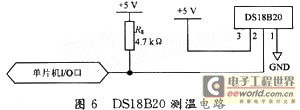
The system uses the DS18B20 single-wire intelligent temperature sensor produced by DALLAS Semiconductor, which is a new generation of intelligent temperature sensors adapted to microprocessors. DS18B20 has two main working modes: parasitic power supply mode and external power supply mode. This system uses the external power supply mode (as shown in Figure 6).
2.2.3 Humidity detection part
Humidity detection uses HS1101 humidity sensor, which is a variable capacitance relative humidity sensor produced by HUMIREL and adopts a unique process design.
HS1101 measures humidity by placing HS1101 in a 555 oscillation circuit and converting the change in capacitance into a voltage-frequency signal that can be directly collected by a microprocessor.
The designed circuit is shown in Figure 7.
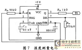
The 555 chip external resistors R20, R19 and HS1101 form a charging circuit for HS1101. Terminal 7 is short-circuited to ground through the transistor inside the chip to realize the discharge circuit for HS1101, and pins 2 and 6 are connected to the on-chip comparator to form a multi-harmonic oscillator, where R20 must be very small relative to R19, but must not be lower than a minimum value. R18 is a protective resistor to prevent short circuit.
HS1101 acts as a variable capacitor, connecting pins 2 and 6. Pin 1 acts as the short-circuit pin of R20. The equivalent capacitance of HS1101 is charged through R19 and R20 to reach the upper limit voltage (approximately 0.67 VCC, time is recorded as T1), at which time pin 3 of 555 changes from high level to low level, and then starts to discharge through R19. Since R20 is short-circuited to ground by pin 7, it only discharges to the trigger boundary (approximately 0.33 VCC, time is recorded as T2), at which time pin 3 of 555 chip changes to high level. The sensor is continuously charged and discharged through two different resistors R19 and R20 to generate square wave output. It can be concluded that:

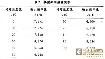
It can be seen that there is a certain linear relationship between the relative humidity of the air and the output frequency of the 555 chip. Table 2 shows the typical frequency-humidity relationship (reference point: 25°C, relative humidity: 55%, output frequency: 6.660 kHz). The frequency of the 555 chip can be collected by the microprocessor, and then the relative humidity value can be obtained by looking up the table. In order to better improve the measurement accuracy, the lower computer will be responsible for collecting the frequency and sending the frequency value to the upper computer for segmented processing.
2.2.4 Temperature and humidity control part
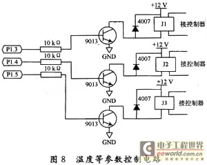
In the monitoring system, in addition to real-time detection of parameters such as temperature and humidity, these parameters also need to be controlled. When the temperature and other measured parameters exceed the user's set value range, the relevant control equipment is started, otherwise the control equipment is turned off. The system uses relays to control the start of ventilation, dehumidification and other equipment. The specific circuit design is shown in Figure 8, where J1 is used to control ventilation equipment, and J2 and J3 are used to control humidity.
3 System Software Design
The monitoring system software design is divided into the software design of the upper computer system and the software design of the lower computer system.
The software of the host computer system includes monitoring management software and CAN adapter software. The on-site monitoring management part mainly uses KingView software to complete the simulation of the on-site measurement points of the warehouse, collect the on-site data of the warehouse, analyze the collected data, automatically calculate the highest, lowest and average temperature values in the warehouse, and can also calculate the highest, lowest and average temperature values of each floor, complete the real-time alarm for over-limit, and realize the operation and control of on-site equipment. For example, start ventilation, dehumidification, spraying and safety protection devices, alarm, cut off power, etc. And automatically generate various reports and charts, establish and store the warehouse's storage history archives and printing functions. The remote monitoring management part mainly completes the functions of remote query of warehouse status, report printing and remote control.
The software design of the CAN adapter is developed using VB language in Windows environment. Due to the protection of Windows, VB cannot directly read and write the parallel port. Another program module is needed to realize the direct reading and writing of the parallel port. The WINIO module is used to solve the reading and writing of the parallel port by VB. At the same time, since the WINIO module does not support system interrupts, it is also necessary to use VB to write threads to query the interrupt status of SJA1000.
The software of the lower computer system includes the CAN node software and the temperature and humidity detection control software. The software design adopts a modular design method. The main programs in the software include the initialization of SJA1000, the message sending program, the message receiving program, the CAN bus error handling program, and the acquisition of field parameters in cooperation with the sensor.
4 Conclusion
This design successfully introduced the CAN bus as a communication network in the overall structural design of the warehouse. The lower computer used the AT89S52 microcontroller and SJA1000 to complete the CAN node design, and the upper computer completed the design of the CAN communication adapter. The upper computer high-level language VB and EPP protocol were used to control SJA1000, which greatly improved the internal rate and real-time performance of the system, and had the advantages of fast processing speed and low cost.
Previous article:Design and implementation of elevator call controller based on CAN bus
Next article:ABS controller development device system and design
- Popular Resources
- Popular amplifiers
- Molex leverages SAP solutions to drive smart supply chain collaboration
- Pickering Launches New Future-Proof PXIe Single-Slot Controller for High-Performance Test and Measurement Applications
- CGD and Qorvo to jointly revolutionize motor control solutions
- Advanced gameplay, Harting takes your PCB board connection to a new level!
- Nidec Intelligent Motion is the first to launch an electric clutch ECU for two-wheeled vehicles
- Bosch and Tsinghua University renew cooperation agreement on artificial intelligence research to jointly promote the development of artificial intelligence in the industrial field
- GigaDevice unveils new MCU products, deeply unlocking industrial application scenarios with diversified products and solutions
- Advantech: Investing in Edge AI Innovation to Drive an Intelligent Future
- CGD and QORVO will revolutionize motor control solutions
- Innolux's intelligent steer-by-wire solution makes cars smarter and safer
- 8051 MCU - Parity Check
- How to efficiently balance the sensitivity of tactile sensing interfaces
- What should I do if the servo motor shakes? What causes the servo motor to shake quickly?
- 【Brushless Motor】Analysis of three-phase BLDC motor and sharing of two popular development boards
- Midea Industrial Technology's subsidiaries Clou Electronics and Hekang New Energy jointly appeared at the Munich Battery Energy Storage Exhibition and Solar Energy Exhibition
- Guoxin Sichen | Application of ferroelectric memory PB85RS2MC in power battery management, with a capacity of 2M
- Analysis of common faults of frequency converter
- In a head-on competition with Qualcomm, what kind of cockpit products has Intel come up with?
- Dalian Rongke's all-vanadium liquid flow battery energy storage equipment industrialization project has entered the sprint stage before production
- Allegro MicroSystems Introduces Advanced Magnetic and Inductive Position Sensing Solutions at Electronica 2024
- Car key in the left hand, liveness detection radar in the right hand, UWB is imperative for cars!
- After a decade of rapid development, domestic CIS has entered the market
- Aegis Dagger Battery + Thor EM-i Super Hybrid, Geely New Energy has thrown out two "king bombs"
- A brief discussion on functional safety - fault, error, and failure
- In the smart car 2.0 cycle, these core industry chains are facing major opportunities!
- Rambus Launches Industry's First HBM 4 Controller IP: What Are the Technical Details Behind It?
- The United States and Japan are developing new batteries. CATL faces challenges? How should China's new energy battery industry respond?
- Murata launches high-precision 6-axis inertial sensor for automobiles
- Ford patents pre-charge alarm to help save costs and respond to emergencies
- Introducing the TI C2000 stack evaluation method
- Note on ATMEGA168 replacing ATMEGA8 microcontroller
- MicroPython's official documentation has been significantly adjusted
- DISP0_CONTRAST is used as GPIO to drive LED
- (Bonus 6) GD32L233 Review - Random Numbers (with software random number generation algorithm)
- Disassembly of a compact portable negative ion generator
- MM32F031 Development Board Evaluation 4: UART and ADC Test
- Half-bridge DC/DC power supply based on LM5036
- Share ESP8266smartconfig source code
- The voltage of HM1548 cannot be raised to 24V. I have tried 10UH inductor and 22UF capacitor, but they are not good. Can someone take a look at it?

 AD8390ARCZ-REEL


 京公网安备 11010802033920号