Overview
:
In recent years, with the proposal of building a conservation-oriented society, the importance of energy conservation and power saving has become increasingly high, especially the energy-saving transformation of large-scale electrical equipment in state-owned enterprises has been strengthened. The number of inverters used in large state-owned enterprises such as oil fields, coal mines, power plants, and steel mills has increased. Especially in oil fields, power electronic equipment such as pumping unit inverters, submersible electric pump inverters, water injection pump inverters and heating power supplies have been widely promoted and used in oil fields. According to the particularity of field operations in oil field production
,
the distance between each device is relatively far, but relatively concentrated, so centralized control based on various field buses is becoming more and more necessary.
The
CAN
bus has shown outstanding advantages in the centralized management and control of frequency conversion equipment. Its ultra-long-distance transmission and super anti-interference performance are unmatched by other buses. Another important point is that in the entire control system, there is no master-slave networking topology, which is convenient for adding and reducing communication nodes.
The medium
and low voltage inverters and heating power supplies of Shandong Xinfengguang Electronic Technology Development Co., Ltd. have stable performance, complete protection functions, and
RS232
and
RS485
communication interfaces. As of
June
2007
, the total number of units in use in Daqing Oilfield and Shengli Oilfield exceeded
700
, of which Shengli Oilfield has about
500
units, and the number is increasing rapidly. In addition, Xinxiang Pharmaceutical Group also has hundreds of fermentation tank inverter equipment. This is a very high market share for inverters of the same brand in the same field. This provides a great market condition for the remote centralized monitoring system based on
the CAN
bus, and it is necessary to promote it. In addition, the system can be flexibly applied to production sites with multiple inverter equipment at the same time.
CAN
bus introduction:
The communication protocol used by
CAN
is
CSMA
/
CD
protocol (
Carrier Sense Multiple Access/
Collision
Detection
). Each node on the network always monitors whether the bus is idle when sending data to the bus. If no conflict is detected, that is, the bus is in an idle state, then each node sends data to the bus and each node has an equal opportunity, that is, carrier sense multiple access. If two nodes send data to the bus at the same time, the node detects a conflict and makes corresponding lossless arbitration processing. That is, after the conflict, the data can remain unchanged
,
continue to monitor the bus, and wait for the next transmission.
The CAN
protocol is a protocol based on message format rather than a protocol based entirely on node
ID
transmission, which abolishes the traditional station address encoding. Based on this protocol: the transmission of messages is not only transmitted from one node to another according to the address, but also multicast and broadcast can be realized. During broadcasting, each node in the system can receive the data transmitted on the bus and confirm whether each message can be received correctly. At the same time, each node can determine whether the received data should be saved or discarded immediately. The error detection in
the
CAN
communication process mainly includes: response error, format error, bit error, and fill error. The main error states include error activation, error recognition, bus shutdown, etc.
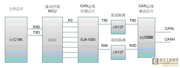
Figure
1
System topology
Inverter node information collection:
Node information mainly refers to the various operating parameters and operating status of the inverter. The commonly used parameter settings of wind and solar inverters are: operating frequency, maximum frequency, starting frequency, acceleration time, deceleration time, rated current,
V/F
curve selection, open loop
/
closed loop setting, multi-speed setting, actual input current and voltage, actual output current and voltage, low frequency compensation; in addition, there are a variety of fault protection monitoring: short circuit protection (instantaneous current exceeds
1.8
times of the rated current), overcurrent protection (current exceeds
1.5
times of the rated current and lasts for
1 minute
), overvoltage protection (input voltage exceeds
1.2
times of the rated voltage), undervoltage protection (input voltage is lower than
0.8
times
of the rated voltage
), temperature rise protection (inverter internal temperature is higher than
7
5
degrees Celsius
), phase loss protection, external abnormality protection, etc.
There are currently two acquisition methods: For the original model, the main control chip is
N
87C 196MC
, the external communication mode of the main control board is
RS485
, so an
RS485
-
CAN
conversion circuit
must be added
when communicating with
the CAN
bus.

Figure
2
Schematic diagram of node information collection
With the upgrading of products,
the application
of
DSP
makes
communication
easier
.
The 2407A
chip integrates
a
CAN
communication interface, so the above circuit can be omitted. The upgraded wind and solar inverter
will make
CAN
bus communication much simpler.
Data transmission and conversion:
After the data is sent to the bus, it must be transmitted through the medium. Since
the
CAN
protocol itself optimizes the error control algorithm, it does not have high requirements for the medium. An ordinary twisted pair can achieve this.
The transmission distance is 10km
. However, considering the absolute reliability of inverter operation and equipment control, we
Use twisted pair cables within a
5km
transmission range.
At 5km,
optical fiber is used as the intermediate transmission medium to improve anti-interference capabilities.
When CAN
is transmitted to the control computer, an external level converter must be added to complete the data exchange with the main control computer. The conversion principle is shown in Figure
2.
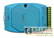
In addition, there are relatively mature products of this type of conversion device in the current market. As shown in Figure
3
, the conversion interface launched by Zhou Ligong is basically a transparent device for users and is relatively convenient to use.

Figure
3 CAN-232
conversion interface card
Human Machine Interface:
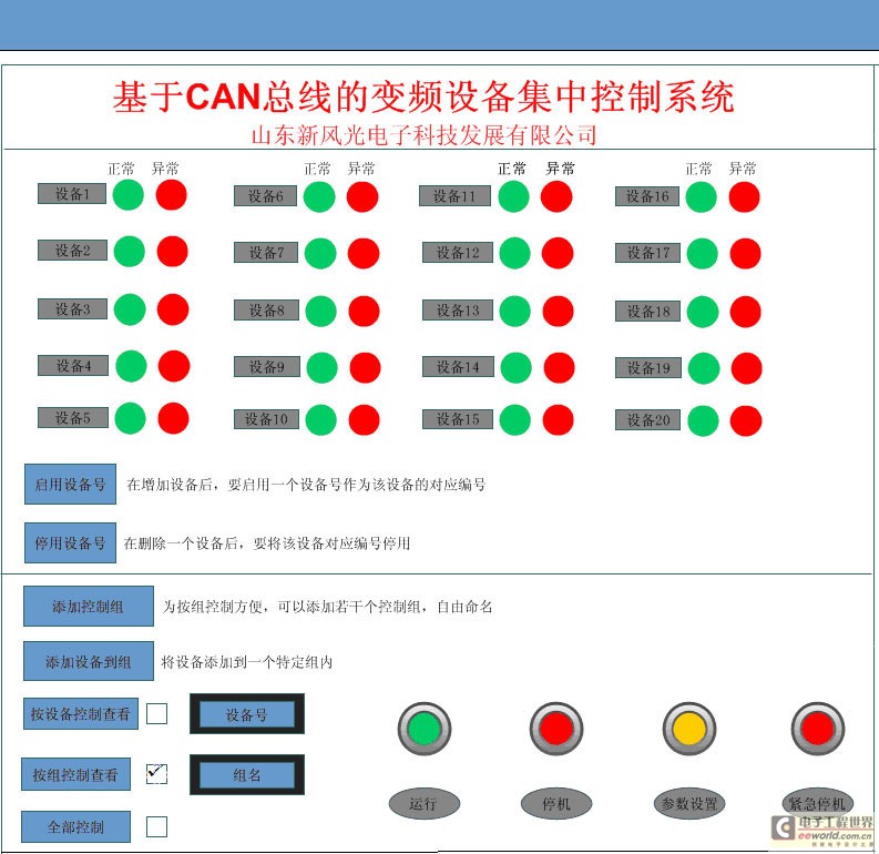
The monitoring program of the monitoring computer is configured in two types: a specific system and a general system. The following is a general-purpose
centralized monitoring human-machine interface for
20
sets of equipment. The entire human-machine interface system consists of two parts: the equipment monitoring part and the equipment control part.
If a device is added to the system, a device number can be set for the device manually and stored in the system, that is, a device number is enabled. After a device is removed from the system, the device number can be deleted and reused. The enabled device number is the operable number, otherwise the number is inoperable. When the device is running normally, the green light is on when it is normal, and the red light is on when an abnormality occurs.
For the convenience of operation, multiple devices in the whole system can be divided into several control groups for management. When operating by group, all devices in the group can be operated at the same time: start, stop, emergency stop, parameter setting, frequency adjustment, etc. The common parameter settings in the group can be viewed at the same time. Double-clicking the device number can also view the operating status and operating curve by device, and can also conveniently perform various operations on a single device. All devices in the system can also be operated at the same time.

Figure
4
Schematic diagram of human-machine interface
Conclusion:
In the whole system, the design is based on the principle of flexibility and convenience, and is designed to adapt to multiple work sites. After a hardware node fails, the data can be uploaded in the shortest time. The host computer can also observe and control each device in real time, achieving the purpose of remote monitoring, facilitating operation, enhancing system reliability, and saving production costs.
Previous article:Research on motion control system of humanoid robot based on CAN bus and dual sensors
Next article:Design of underground multi-parameter monitoring system based on CAN bus
- Popular Resources
- Popular amplifiers
Latest Industrial Control Articles
- Molex leverages SAP solutions to drive smart supply chain collaboration
- Pickering Launches New Future-Proof PXIe Single-Slot Controller for High-Performance Test and Measurement Applications
- CGD and Qorvo to jointly revolutionize motor control solutions
- Advanced gameplay, Harting takes your PCB board connection to a new level!
- Nidec Intelligent Motion is the first to launch an electric clutch ECU for two-wheeled vehicles
- Bosch and Tsinghua University renew cooperation agreement on artificial intelligence research to jointly promote the development of artificial intelligence in the industrial field
- GigaDevice unveils new MCU products, deeply unlocking industrial application scenarios with diversified products and solutions
- Advantech: Investing in Edge AI Innovation to Drive an Intelligent Future
- CGD and QORVO will revolutionize motor control solutions
MoreSelected Circuit Diagrams
MorePopular Articles
- Innolux's intelligent steer-by-wire solution makes cars smarter and safer
- 8051 MCU - Parity Check
- How to efficiently balance the sensitivity of tactile sensing interfaces
- What should I do if the servo motor shakes? What causes the servo motor to shake quickly?
- 【Brushless Motor】Analysis of three-phase BLDC motor and sharing of two popular development boards
- Midea Industrial Technology's subsidiaries Clou Electronics and Hekang New Energy jointly appeared at the Munich Battery Energy Storage Exhibition and Solar Energy Exhibition
- Guoxin Sichen | Application of ferroelectric memory PB85RS2MC in power battery management, with a capacity of 2M
- Analysis of common faults of frequency converter
- In a head-on competition with Qualcomm, what kind of cockpit products has Intel come up with?
- Dalian Rongke's all-vanadium liquid flow battery energy storage equipment industrialization project has entered the sprint stage before production
MoreDaily News
- Allegro MicroSystems Introduces Advanced Magnetic and Inductive Position Sensing Solutions at Electronica 2024
- Car key in the left hand, liveness detection radar in the right hand, UWB is imperative for cars!
- After a decade of rapid development, domestic CIS has entered the market
- Aegis Dagger Battery + Thor EM-i Super Hybrid, Geely New Energy has thrown out two "king bombs"
- A brief discussion on functional safety - fault, error, and failure
- In the smart car 2.0 cycle, these core industry chains are facing major opportunities!
- The United States and Japan are developing new batteries. CATL faces challenges? How should China's new energy battery industry respond?
- Murata launches high-precision 6-axis inertial sensor for automobiles
- Ford patents pre-charge alarm to help save costs and respond to emergencies
- New real-time microcontroller system from Texas Instruments enables smarter processing in automotive and industrial applications
Guess you like
- [Erha Image Recognition Artificial Intelligence Vision Sensor] 3. General Settings and Face Recognition
- Prize-winning quiz: Find the "know-it-all" expert on Intel Vision Accelerated Design online
- 【ufun learning】Part 4: Serial port printing output
- TI Signal Chain and Power Q&A Series Live Broadcast - Gate Driver Special Live Broadcast with Prizes in Progress!
- Main application categories of millimeter wave radar
- pybL development board pinout
- Npn tube, Iceo is the reverse cutoff current, C and E are both N, where does the reverse come from, what does the reverse here mean...
- EEWORLD University ---- MSP CapTIvate Adaptive Sensor PCB Design Guide
- Children's Day is coming, what do you want to reminisce about?
- 【Running posture training shoes】No.009-Work submission


 HA7-2525-5


 京公网安备 11010802033920号