1. Introduction
Nowadays, hydraulic servo systems are widely used in automation fields such as industry and national defense due to their advantages of light weight, small size, and large torque generation. However, due to factors such as oil leakage and oil contamination, hydraulic servo systems generally have time-varying parameters, nonlinearity, and especially nonlinearity of flow in valve-controlled power mechanisms. With the increasing requirements for control accuracy, higher and higher requirements are also placed on hydraulic servo control technology. Traditional PID control is difficult to achieve satisfactory control effects. To address this problem, many different modern control strategies have emerged in recent years, such as neural network control, adaptive control, fuzzy control, and predictive control. These control methods have made great progress in theory, but there are still some practical problems that need to be solved in hydraulic servo control [1].
Fuzzy control does not require an accurate mathematical model of the controlled object and can introduce expert experience, so it has good practicality. However, it is not easy to eliminate steady-state errors using fuzzy control alone, and it has high requirements on the controller's computing performance [2]. The PID algorithm is simple and can effectively eliminate steady-state errors. In this regard, this paper combines fuzzy control with PID control, and uses fuzzy control to correct PID parameters in real time, which improves the control accuracy and robustness of the system and has good practicality.
2. Hydraulic position servo system

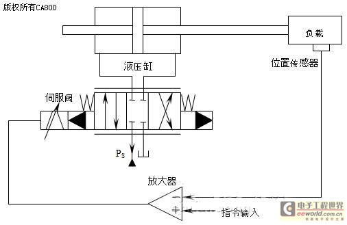
Figure 1 Structure diagram of hydraulic position servo system
As shown in Figure 1, the hydraulic position servo system consists of an amplifier, an electro-hydraulic servo valve, a hydraulic cylinder, a load, and a position sensor. The input signal is amplified and sent to the electro-hydraulic servo valve. The low-power electrical signal is converted into a valve core displacement signal through the servo valve, and then converted into hydraulic signals such as flow and pressure. These signals finally drive the hydraulic cylinder to drive the load to complete the specified action.
Because the electro-hydraulic servo valve realizes the two functions of electro-hydraulic signal conversion and hydraulic power amplification, it plays the role of a bridge in the servo system and is the heart of the system. In this article, the position servo system adopts a two-stage electro-hydraulic servo valve with a moving iron torque motor, nozzle and baffle.
Based on the voltage, magnetic circuit and motion equation of the torque motor, the relationship between the nozzle flapper displacement and the motor deflection angle, and the motion equation and flow equation of the main valve (symmetrical four-way slide valve) [3], the transfer function of the electro-hydraulic servo valve can be derived as follows:

In the formula: ω
sv
is the natural frequency of the servo valve; ξ
sv
is the damping ratio; Kq is the servo valve flow gain, which should be determined according to the actual no-load flow under the actual oil supply pressure, that is
 , qn is the rated flow of the servo valve, ps is the actual oil supply pressure, psn is the specified valve pressure drop of the servo valve, generally psn=7MPa, and In is the rated current of the servo valve.
In addition, the actuator in this article is a hydraulic cylinder, and the load is pure inertia, without considering factors such as frame stiffness. The transfer function of the valve-controlled cylinder can be derived from the motion equation as follows:

Where: Q0 is the no-load flow rate of the servo valve,
 , the symbols have the same meaning as before; P is the effective area of the hydraulic cylinder piston; ωh is the hydraulic natural frequency; ξh is the hydraulic damping ratio;
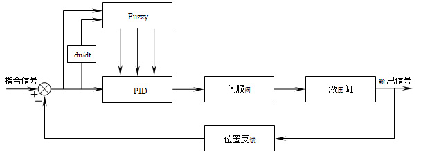
Through the above derivation, the mathematical model (1) (2) of the hydraulic controlled part in the hydraulic position servo control system is obtained. Then, on the basis of using PID control, the three parameters of PID proportion, integration and differentiation are corrected through fuzzy control. In this way, the system can be guaranteed to be in the optimal state under different conditions, thereby improving the system control accuracy, and having better real-time and robustness. As shown in Figure 2, the block diagram of the designed hydraulic position servo fuzzy PID control system.

Figure 2 Hydraulic position servo fuzzy PID control system
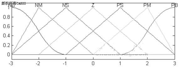
This paper uses fuzzy control method to achieve online adjustment of PID parameters. The input of fuzzy control is error and error change rate, and the output is the adjustment amount of three PID parameters △kp, △ki and △kd. According to the basic domain of the hydraulic position servo system setting [0.6, 0.6], the basic domain of is [0.3, 0.3], and the corresponding fuzzy domain is {-3, -2, -1, 0, 1, 2, 3}, so the quantization factor is now the fuzzy set E of error e and error change rate ec, EC = {NB, NM, NS, Z, PB, PM, PB}, and its membership function is shown in Figure 3:

Figure 3. Member number function of error
The fuzzy domains of the fuzzy control outputs △kp, △ki and △kd are {-3,-2,-1,0,1,2,3}, {-0.06,
The membership functions of the three output variables are the same as those of the input error and error change rate, and all use trigonometric functions, which are not listed here one by one.
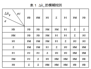
After fuzzifying the precise quantity, the fuzzy rule tables of the fuzzy output variables △kp, △ki and △kd can be derived respectively according to the fuzzy sets and membership functions of each quantity by using MAX-MIN fuzzy reasoning. It is very important to consider the effects of the three PID parameters and their relationship based on theoretical knowledge and engineering experience.


According to the fuzzy output inferred by the fuzzy rules in Tables 1, 2, and 3, the actual accurate values of the three PID parameters can be obtained through defuzzification, thereby realizing online adjustment of the PID. In order to achieve better fuzzy control effect, this paper uses the median defuzzification method.
4. MATLAB simulation results
Select the DYC1-40L electro-hydraulic servo valve, whose parameters are: q
n
=40L/min, actual oil supply pressure

 . The hydraulic cylinder parameters are:
 . Simulink is used in Matlab to establish the step response simulation model of PID control and fuzzy PID control, and white noise interference with an amplitude of 1 is added to simulate the time variation of the model. The simulation waveform is as follows:
 5. Conclusion
The simulation results show that when the PID setting parameters are the same, adding fuzzy control to modify the PID parameters in real time can better control the controlled object. As can be seen from Figures 4 and 5, once the PID parameters are fixed, their applicability under time-varying conditions is greatly restricted, while the fuzzy PID can keep the control performance in the optimal state through online self-adjustment of parameters, with better control accuracy and robustness. In addition, when adjusting the fuzzy control parameters, special attention should be paid to the role of the quantization factor and the proportional factor.
Previous article:Fuzzy Intelligent Implementation of Temperature Control System of Heating Furnace
Next article:Speed sensorless vector control system for mining locomotive
- Popular Resources
- Popular amplifiers
- Molex leverages SAP solutions to drive smart supply chain collaboration
- Pickering Launches New Future-Proof PXIe Single-Slot Controller for High-Performance Test and Measurement Applications
- CGD and Qorvo to jointly revolutionize motor control solutions
- Advanced gameplay, Harting takes your PCB board connection to a new level!
- Nidec Intelligent Motion is the first to launch an electric clutch ECU for two-wheeled vehicles
- Bosch and Tsinghua University renew cooperation agreement on artificial intelligence research to jointly promote the development of artificial intelligence in the industrial field
- GigaDevice unveils new MCU products, deeply unlocking industrial application scenarios with diversified products and solutions
- Advantech: Investing in Edge AI Innovation to Drive an Intelligent Future
- CGD and QORVO will revolutionize motor control solutions
- Innolux's intelligent steer-by-wire solution makes cars smarter and safer
- 8051 MCU - Parity Check
- How to efficiently balance the sensitivity of tactile sensing interfaces
- What should I do if the servo motor shakes? What causes the servo motor to shake quickly?
- 【Brushless Motor】Analysis of three-phase BLDC motor and sharing of two popular development boards
- Midea Industrial Technology's subsidiaries Clou Electronics and Hekang New Energy jointly appeared at the Munich Battery Energy Storage Exhibition and Solar Energy Exhibition
- Guoxin Sichen | Application of ferroelectric memory PB85RS2MC in power battery management, with a capacity of 2M
- Analysis of common faults of frequency converter
- In a head-on competition with Qualcomm, what kind of cockpit products has Intel come up with?
- Dalian Rongke's all-vanadium liquid flow battery energy storage equipment industrialization project has entered the sprint stage before production
- Allegro MicroSystems Introduces Advanced Magnetic and Inductive Position Sensing Solutions at Electronica 2024
- Car key in the left hand, liveness detection radar in the right hand, UWB is imperative for cars!
- After a decade of rapid development, domestic CIS has entered the market
- Aegis Dagger Battery + Thor EM-i Super Hybrid, Geely New Energy has thrown out two "king bombs"
- A brief discussion on functional safety - fault, error, and failure
- In the smart car 2.0 cycle, these core industry chains are facing major opportunities!
- The United States and Japan are developing new batteries. CATL faces challenges? How should China's new energy battery industry respond?
- Murata launches high-precision 6-axis inertial sensor for automobiles
- Ford patents pre-charge alarm to help save costs and respond to emergencies
- New real-time microcontroller system from Texas Instruments enables smarter processing in automotive and industrial applications
- Testing methods and diagnostic analysis for DSP-containing circuit boards
- Get the relevant information required by LSM6DSOX+STEVAL-MKI109V3 contestants (including official information and moderator reviews)
- ZigBee terminal (low power device)
- MCU external crystal and oscillation circuit
- [RVB2601 Creative Application Development] GPIO Simulation SPI Serial Port
- Embedded Qt-Table Usage Test
- I found a very useful Renesas RL78 offline programmer.
- Porting appweb
- Disassembly of the knockoff TWS headset charging box
- Oscilloscope usage video collection (Chinese and English 2 versions)

 NJU7064V(TE1)


 京公网安备 11010802033920号