According to the idea of model reference adaptive control (MRAC), the MRAC model of CNC machine tool cutting process was established, and then the dynamic process of the model was simulated. At the same time, the feedback closed-loop control and open-loop control of the machining process were simulated respectively, and the three simulation results were compared. From the simulation results, it can be seen that the MRAC machine tool cutting performance index is the best.
1 Working principle of MRAC
The MRAC of CNC machine tools takes the cutting process completed by the machine tool, tool, and workpiece system as the adjustment object. The principle structure of the control system is shown in Figure 1. In addition to the position and speed control loops of general CNC machine tools, it also adds an MRAC feedback loop. When the system is disturbed by various random factors, the state parameters of the cutting process change immediately. The values of these parameters are detected by sensors at any time and converted. In the MRAC control unit, they are judged and compared with the given evaluation indicators or constraints (i.e., the expected performance indicators) to obtain the performance indicator deviation, and then the correction signal is output to the host CNC to correct the input parameters of the system, so that the cutting process is transformed to the predetermined indicators and conditions to achieve the best state.
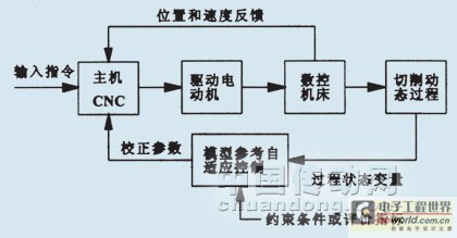
Figure 1 MRAC system structure of CNC machine tools
2 Establishment of MRAC model for machine tool cutting
The MRAC model of the machine tool cutting process is shown in Figure 2, which consists of a servo mechanism, a cutting process, a reference model adjustment mechanism, a feedforward device, and a feedback device.

Fig.2 Block diagram of MRAC model of cutting process
The servo link can be represented by a two-section system:
 (1)
(1)
Where: s is the operator of Laplace transform; u is the servo input (V); Kn is the servo gain (mm/(V·s)); ωn is the natural frequency of the servo system (rad/s); v is the feed speed (mm/s); ξ is the damping coefficient; f is the feed amount (mm/r), which can be expressed as:
 (2)
(2)
Where: n is the spindle speed (r/min); A is the number of teeth of the tool during milling, and p=1 during turning.
Considering that the reference model adjustment mechanism is used as an ideal performance indicator, this link is still the same as the servo mechanism link, that is,
The static cutting force Fs in the cutting process can be expressed as:
 (3)
(3)
Where: Ks is the cutting force (N/mm2), m is the index (generally m<1), Ks and m depend on the workpiece material and tool shape; a is the back cutting depth (mm).
According to different machining process characteristics, the dynamic process of Fs can also be expressed by equation (3). Assuming m=1, its dynamic process can be expressed by a first-order system:
 (4)
(4)
Where: τ is the time constant.
The feedforward device and feedback device in the model are both proportional links with a proportional coefficient of K.
Therefore, according to the composition of the above system links, the mathematical control model of MRAC in the cutting process can be obtained as shown in Figure 3.
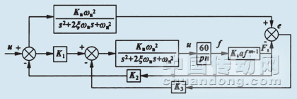
Figure 3 MRAC mathematical model of cutting process

Figure 4 MRAC simulation diagram
3 Cutting performance of MRAC during machining process
In the process of machine tool processing, the quality of cutting performance will not only have a great impact on the quality of parts, but also easily damage the tool. The cutting process of the machine tool, tool, and workpiece system is an unstable process. It is often disturbed by many uncertain factors in the outside world, causing the state parameters of the cutting process to change at any time. If it is not adjusted in time, the cutting performance will be greatly reduced. Through MRAC adjustment, the parameters of the cutting performance can be kept in a stable state. Now take the example of the constant cutting force at the set value during machine tool processing to illustrate that MRAC can adjust the cutting force in time when it is disturbed by external factors (taking the change of back cutting amount as an example) so that it is always in the expected cutting force. According to the experiment, the parameters in the known processing model are Ks=1500N/mm2, n=600r/min, Kn=0.95mm/(V·s), ξ=0.68, p=1, m=1, ωn=22rad/s, the back cutting amount changes from 1 to 3mm according to the sine curve, and the expected value of the cutting force is set to 1000N. Substituting the above parameters into the mathematical control model of FIG. 3 , the simulation diagram shown in FIG. 4 can be obtained by using the MATLAB/SIMULINK tool, and the simulation result is shown in FIG. 5 .
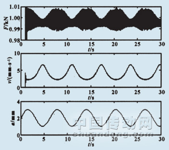
Figure 5 Simulation results
From the simulation results in Figure 5, we can see that the change in back cutting depth is exactly opposite to the change in feed speed, that is, if the back cutting depth increases, the feed speed is reduced to keep the cutting force constant at 1000 N, and vice versa. Therefore, the MRAC system achieves constant force control during the machining process by automatically and accurately adjusting the feed speed of the machining process.
4 Comparison of cutting performance between MRAC and traditional closed-loop and open-loop control
4.1 Cutting performance simulation of traditional closed-loop and open-loop control systems
Referring to MRAC simulation Figure 4, closed-loop and open-loop simulation diagrams can be established respectively (open-loop simulation diagram has no feedback, and the rest is the same as closed-loop simulation, which can be referred to the closed-loop diagram, which is omitted in this article), as shown in Figure 6, and the simulation results are shown in Figures 7 and 8. From the simulation results, it can be seen that the cutting force of closed-loop control can basically keep it constant at about 1000N, while the cutting force of open-loop control is far away from 1000N.
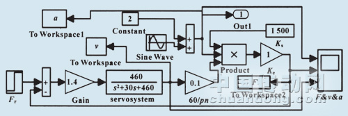
Figure 6 Closed-loop control simulation diagram
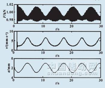
Figure 7 Closed-loop control simulation results
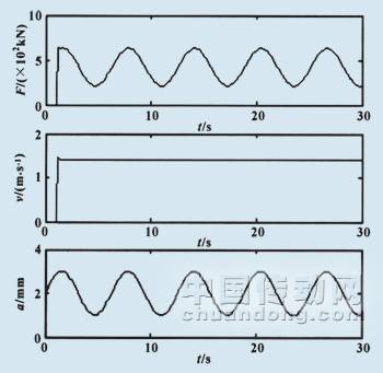
Figure 8 Open-loop control simulation results
4.2 Analysis of cutting performance errors among three control systems
From the simulation results of the above three controls, their machining and cutting performance errors can be roughly analyzed. First, the error of the MRAC system can be roughly obtained:

The error of the closed-loop control system can be obtained:


The error of the open-loop control system can be obtained:

Where: E(X) and E(S) represent the upper and lower deviations of the error respectively.
By comparison, it can be found that the MRAC system has the smallest error, so MRAC can enable the lathe to maintain good cutting performance during processing better than traditional closed-loop and open-loop systems.
5 Conclusion
Through MATLAB/SIMULINK simulation and experiments, it is proved that MRAC can keep the cutting performance of CNC machine tools in a good and stable state. In view of this, MRAC can also be applied to other automation equipment. It should be noted that conventional MRAC can only be applied to minimum phase systems, while the machining process may be a non-minimum phase system under certain sampling conditions, with unstable inverse zero points. At this time, a modified MRAC solution is required.
Previous article:Design strategy for intelligent video surveillance application system
Next article:Application Research of Mobile Robot Based on S3C44B0X
- Popular Resources
- Popular amplifiers
- Molex leverages SAP solutions to drive smart supply chain collaboration
- Pickering Launches New Future-Proof PXIe Single-Slot Controller for High-Performance Test and Measurement Applications
- CGD and Qorvo to jointly revolutionize motor control solutions
- Advanced gameplay, Harting takes your PCB board connection to a new level!
- Nidec Intelligent Motion is the first to launch an electric clutch ECU for two-wheeled vehicles
- Bosch and Tsinghua University renew cooperation agreement on artificial intelligence research to jointly promote the development of artificial intelligence in the industrial field
- GigaDevice unveils new MCU products, deeply unlocking industrial application scenarios with diversified products and solutions
- Advantech: Investing in Edge AI Innovation to Drive an Intelligent Future
- CGD and QORVO will revolutionize motor control solutions
- Innolux's intelligent steer-by-wire solution makes cars smarter and safer
- 8051 MCU - Parity Check
- How to efficiently balance the sensitivity of tactile sensing interfaces
- What should I do if the servo motor shakes? What causes the servo motor to shake quickly?
- 【Brushless Motor】Analysis of three-phase BLDC motor and sharing of two popular development boards
- Midea Industrial Technology's subsidiaries Clou Electronics and Hekang New Energy jointly appeared at the Munich Battery Energy Storage Exhibition and Solar Energy Exhibition
- Guoxin Sichen | Application of ferroelectric memory PB85RS2MC in power battery management, with a capacity of 2M
- Analysis of common faults of frequency converter
- In a head-on competition with Qualcomm, what kind of cockpit products has Intel come up with?
- Dalian Rongke's all-vanadium liquid flow battery energy storage equipment industrialization project has entered the sprint stage before production
- Allegro MicroSystems Introduces Advanced Magnetic and Inductive Position Sensing Solutions at Electronica 2024
- Car key in the left hand, liveness detection radar in the right hand, UWB is imperative for cars!
- After a decade of rapid development, domestic CIS has entered the market
- Aegis Dagger Battery + Thor EM-i Super Hybrid, Geely New Energy has thrown out two "king bombs"
- A brief discussion on functional safety - fault, error, and failure
- In the smart car 2.0 cycle, these core industry chains are facing major opportunities!
- The United States and Japan are developing new batteries. CATL faces challenges? How should China's new energy battery industry respond?
- Murata launches high-precision 6-axis inertial sensor for automobiles
- Ford patents pre-charge alarm to help save costs and respond to emergencies
- New real-time microcontroller system from Texas Instruments enables smarter processing in automotive and industrial applications
- Keysight Technologies Award-winning Live Broadcast: Oscilloscope Applications and Techniques in General Electronic Measurements
- [NXP Rapid IoT Review] + 3. A First Look at Rapid IoT Studio
- [Allwinner heterogeneous multi-core AI intelligent vision V853 development board evaluation] error: '%s' directive argument is null
- Design of high efficiency and high dimming ratio LED constant current drive circuit
- Has anyone used LT3751 to boost 400V?
- [Voice and vision module based on ESP32S3] Hardware design, debugging and progress-serial port circuit-2
- rfeasylinkRx initialization problem solved
- This mini motorcycle is so cool!
- Ask about the issue of emission exceeding the standard
- What do phase, displacement, sinusoidal light, and gradient light mean in 3D scanners?

 5962-8687701Q2A


 京公网安备 11010802033920号