0 Introduction
Capacitive sensors are a type of sensor that converts the measured non-electrical quantity changes into capacitance changes. Due to its advantages of high sensitivity, low power consumption, and small temperature drift, it is widely used in pressure, humidity, temperature, acceleration and other measurements. The small size of MEMS (micro-electromechanical system) sensors determines that the capacitance value of sensitive capacitors cannot be large, generally in the order of pF, while the changes in micro-capacitance caused by these physical quantities are even smaller, generally in the order of fF or even aF. Such a small change is a challenge to the design of detection circuits. The traditional method of using discrete components to build detection circuits will not be able to adapt to the trend of sensor capacitance decreasing, so it is necessary to design matching interface integrated circuits. Commonly used low-value capacitance measurement circuits convert capacitance changes into voltage or frequency. At present, most foreign MEMS sensor manufacturers use switched capacitor circuits as the interface of capacitance signals. The characteristics of this circuit are high precision and can achieve high integration with sensors, but the circuit structure is relatively complex and requires high process accuracy. Secondly, the oscillation method is used to convert sensitive capacitance changes into frequency or period. The circuit is simple and easy to implement. The output frequency signal has the characteristics of quasi-digital output, which is easy to measure. The circuit introduced in this article is based on this principle.
1Microcapacitance detection
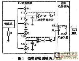
Different from the derived Schmitt trigger-based capacitance detection method, in order to avoid the output frequency being affected by power supply voltage, temperature changes and process fluctuations, the micro-capacitive sensor detection circuit developed by this laboratory designed a difference frequency circuit based on the relaxation oscillator, and its module schematic diagram is shown in Figure 1. This paper tests and analyzes the pipeline chip of the sensitive capacitance detection circuit, builds the entire circuit of the structure shown in Figure 1, and simulates and tests the temperature drift characteristics of the circuit.

2 Analysis and Improvement of Interface Circuit
2.1 Oscillator Circuit
Figure 2 is a sensitive capacitor oscillator circuit that has been taped out in our laboratory. The circuit consists of a turn-on circuit, a constant current source, a CMOS switch, a Schmitt trigger, and an inverter.

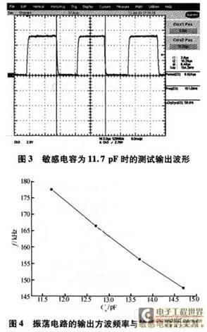
As shown in Figures 3 and 4, the circuit realizes that the frequency of the output waveform is inversely proportional to the change of the sensitive capacitance. Reading the frequency from the output end of the oscillator can fully detect the change of the sensor capacitance. However, there are two problems: one is that the output frequency is too large, which is not convenient for the microcontroller to read; the other is that the output frequency is still affected by the power supply voltage, temperature changes and process fluctuations.

2.2 Difference Frequency Circuit
The difference frequency function is realized by using a D flip-flop in the detection circuit. The D flip-flop is a CMOS master-slave flip-flop triggered by the falling edge. The waveform converted by the sensitive capacitor is input from the D terminal, and the waveform converted by the reference capacitor is input from the CK terminal. The output is the frequency difference between the two waveforms. This can improve the sensitivity of the circuit and improve the influence of temperature and power supply voltage suppression on the circuit performance of the unilateral circuit.
Next, we analyze the difference frequency principle of the D flip-flop. According to the conditions set above, the signal frequency is greater than the clock frequency, and the difference between the period of the input signal and the period of the clock signal is defined as △T, that is,

First, assume that there is an integer such that the waves satisfy the following relationship:

At t0, Vin and Vck are both falling edges, and Vout should follow the original state of Vck to output a high level. Then, according to △T=Tin-Tck, when the second falling edge of Vck arrives, it is one △T later than the second falling edge of Vin, and Vin is a high level at this time. From the truth table of the falling edge triggered D flip-flop (see Table 1), it can be seen that Vout must output a low level at this time, as shown in Figure 5.

After n cycles, when (n-1)△T≤Tin/2 and n△T>Tin/2, Vin is high when Vck drops, and the output jumps to high. After λTck, Vin has gone through one more cycle than Vck, and reaches the falling edge at the same time again, but Vout is still output at a high level. At (λ+1)Tck, the falling edge of Vck arrives, and Vin is high at this time. Vout jumps to a low level again. Taking the distance between the two falling edges of Vout as the period of Vout, we get

For the case where the rising edge of Vin coincides with the falling edge of Vck at time t0, the analysis is exactly the same as above and the same result can be obtained.
Let's consider a more general case. When Tin is not an integer multiple of △T, it is still assumed that different frequencies are input at time t0, and Vout and Vck are both falling edges at different duty cycles. The analysis process is the same as above. The difference is that after Vout passes through λTck, since Tin is not an integer multiple of △T, Vin and Vck cannot reach the falling edge at the same time again, and the above process cannot be applied to the analysis of the next cycle.
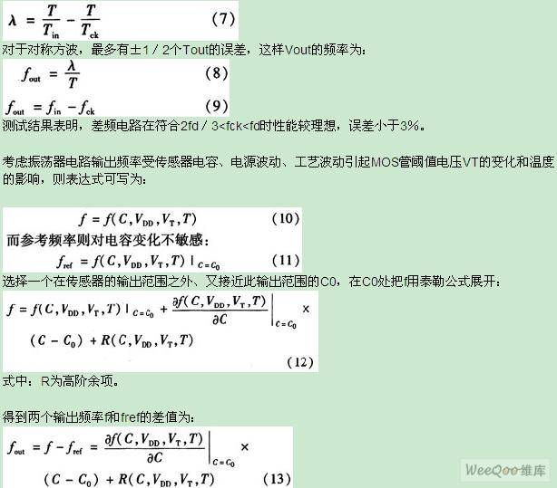
Therefore, consider the relationship between the frequencies of various signals between t0 and t0+T in a relatively long period of time. Vin has T/Tin falling edges, T/Tin or T/Tin+1 rising edges, and Vck has T/Tck falling edges. Vin has T/Tin-T/Tck more cycles than Vck. According to the analysis method, Vout will have T/Tin-T/Tck falling edges, and the Vout cycle can be considered as:

It can be seen from equation (13) that by taking the frequency difference of two identical circuits, the most important item of the influence of power supply, threshold voltage and temperature on frequency is eliminated, which greatly reduces the influence on the capacitance-frequency characteristic.
2.3 Temperature drift characteristics of interface circuit
According to semiconductor theory, the MOS tube threshold voltage can be expressed as:

Substituting -40℃~60℃ into equation (14) and equation (15) respectively, we can finally get the threshold voltage value corresponding to each temperature. It is known that the absolute value of the threshold voltage decreases with the increase of temperature. It is also known that the output frequency is proportional to the process fluctuation, so it can be inferred that the output frequency decreases with the increase of temperature. This will be further verified in the subsequent simulation test.
3 Design and simulation results
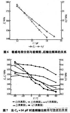
As the interface circuit of the sensor, it is hoped that a stable output frequency can be obtained when the ambient temperature changes. The detection circuit in Figure 1 was simulated and tested when the temperature range was -40℃~60℃ and the reference capacitance was 14.5 pF. It can be found from Figures 6 and 7 that the output frequency is approximately inversely proportional to the temperature, which further verifies the correctness of the above conclusions on the temperature drift characteristic analysis; the temperature coefficient after the difference frequency is about 14 Hz/℃. For the pressure sensor with a sensitivity of 46 fF/hPa, the influence of the sensitivity temperature relative to 10.04: Hz/fF is negligible; there is a distance between the test data curve before the difference frequency and the simulated data curve, which is related to the small current value of the current source in actual work, but does not affect the detection of the overall circuit output result; the absolute value of the slope of the test curve is greater than the absolute value of the slope of the simulation curve, which is because only the threshold voltage change caused by temperature change is considered in the simulation, while the changes in process parameters and device parameters caused by temperature change in actual testing and various interferences in the test environment of the circuit building will affect the test data. This can improve reliability by considering packaging in subsequent work. The results show that the difference frequency structure can filter out most of the influences, and even completely suppress the influence of temperature within the allowable range of accuracy.

The purpose of this circuit is to provide a readout interface for the new generation of sensors in this laboratory. Through the accurate test of the sensor in the early stage, the basic capacitance of the sensor is about 10 pF, which varies from 7 pF to 14 pF. The reference capacitance value of this circuit is 14.5 pF. In order to make the primary output frequency of the sensor greater than the reference frequency and meet the 2fd/3
4 Conclusion
Through SPICE simulation, it can be seen that the improved circuit structure meets the various objectives proposed. Since the circuit uses the change of frequency to reflect the change of sensitive capacitance and has the characteristics of quasi-digital output, the signal can be collected by using only a single-chip microcomputer with counting function.
Process fluctuations will affect the capacitance-frequency conversion characteristics of the circuit, thus causing individual differences in tape-out results. Therefore, each sensor must be calibrated separately so that process fluctuations do not cause deviations in individual sensors.
Previous article:Using difference frequency circuit to suppress temperature drift of microcapacitive sensor detection circuit
Next article:Using difference frequency circuit to suppress temperature drift of microcapacitive sensor detection circuit
- Popular Resources
- Popular amplifiers
- Molex leverages SAP solutions to drive smart supply chain collaboration
- Pickering Launches New Future-Proof PXIe Single-Slot Controller for High-Performance Test and Measurement Applications
- CGD and Qorvo to jointly revolutionize motor control solutions
- Advanced gameplay, Harting takes your PCB board connection to a new level!
- Nidec Intelligent Motion is the first to launch an electric clutch ECU for two-wheeled vehicles
- Bosch and Tsinghua University renew cooperation agreement on artificial intelligence research to jointly promote the development of artificial intelligence in the industrial field
- GigaDevice unveils new MCU products, deeply unlocking industrial application scenarios with diversified products and solutions
- Advantech: Investing in Edge AI Innovation to Drive an Intelligent Future
- CGD and QORVO will revolutionize motor control solutions
- Innolux's intelligent steer-by-wire solution makes cars smarter and safer
- 8051 MCU - Parity Check
- How to efficiently balance the sensitivity of tactile sensing interfaces
- What should I do if the servo motor shakes? What causes the servo motor to shake quickly?
- 【Brushless Motor】Analysis of three-phase BLDC motor and sharing of two popular development boards
- Midea Industrial Technology's subsidiaries Clou Electronics and Hekang New Energy jointly appeared at the Munich Battery Energy Storage Exhibition and Solar Energy Exhibition
- Guoxin Sichen | Application of ferroelectric memory PB85RS2MC in power battery management, with a capacity of 2M
- Analysis of common faults of frequency converter
- In a head-on competition with Qualcomm, what kind of cockpit products has Intel come up with?
- Dalian Rongke's all-vanadium liquid flow battery energy storage equipment industrialization project has entered the sprint stage before production
- Allegro MicroSystems Introduces Advanced Magnetic and Inductive Position Sensing Solutions at Electronica 2024
- Car key in the left hand, liveness detection radar in the right hand, UWB is imperative for cars!
- After a decade of rapid development, domestic CIS has entered the market
- Aegis Dagger Battery + Thor EM-i Super Hybrid, Geely New Energy has thrown out two "king bombs"
- A brief discussion on functional safety - fault, error, and failure
- In the smart car 2.0 cycle, these core industry chains are facing major opportunities!
- The United States and Japan are developing new batteries. CATL faces challenges? How should China's new energy battery industry respond?
- Murata launches high-precision 6-axis inertial sensor for automobiles
- Ford patents pre-charge alarm to help save costs and respond to emergencies
- New real-time microcontroller system from Texas Instruments enables smarter processing in automotive and industrial applications
- Simplify the design of automotive body motor controllers and quickly achieve lightweighting
- Analysis of Directivity and Directivity Coefficient of Microwave Antenna
- Does anyone know how to calculate the input power by first boosting the voltage and then reducing it?
- Why do I/O ports of microcontrollers need drivers?
- Talking about modification, I added a HUD head-up display, and the effect is good!
- There is a constant current source circuit. The simulation is fine, but the actual circuit is incorrect. Can you help me take a look? Thank you!
- The boost circuit is unstable, what is the reason?
- Wireless PLC remote download 4-20ma wireless transmission 0-5v wireless transmission analog quantity wireless transmission solution
- FPGA most downloaded related materials
- What does it mean to connect an isolated 485 transceiver and a non-isolated transceiver in parallel?

 5962-9080801MHA


 京公网安备 11010802033920号