Today, more and more appliance manufacturers are adopting variable speed permanent magnet (PM) synchronous motors to improve energy efficiency and add features to their products. Industrial drive manufacturers have long recognized the high efficiency and high power-to-weight ratio of PM motors, but recent advances in control electronics have enabled widespread adoption of PM motors by appliance manufacturers.
Field-oriented control (FOC) using only DC link current feedback technology minimizes system cost and is very attractive for appliance drive applications. Sinusoidal control of the motor produces smooth torque output with low acoustic noise. Therefore, FOC is suitable for use in devices such as fans, pumps, washers and dryers where low noise and high energy efficiency are important.
Many appliances such as air conditioners and washer-dryers must independently control the speed of two motors to optimize their performance. The traditional approach used in these systems is to use a motor control processor with a serial communication link to achieve synchronization. However, if two motors can be controlled by a single device, the hardware and system design can be greatly simplified. A recently introduced appliance control platform can control two PM AC motors simultaneously using only DC link current feedback technology. The chip uses an embedded FOC algorithm to reduce development time and promote rapid adoption of this technology by appliance manufacturers.
No
Sensor
Implementation of motor control algorithms
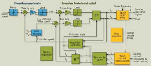
FOC is common in industrial drive systems, which generally use encoders or resolvers to measure the rotor position. The closed-loop current control algorithm uses the rotor's angular coordinates to correct the motor current and rotor flux to maximize torque output. Advanced rotor position estimation algorithms in appliance control systems do not require the use of high-resolution position sensors (Figure 1).

Figure 1: Field-oriented control (FOC) systems eliminate the need for position sensors by using DC-link current feedback techniques.
The estimation algorithm obtains the rotor flux position of the PM based on the motor model using winding voltages and currents. This approach is very suitable because the magnets on the rotor determine the position of the rotor flux. The winding current measurement data is obtained from the DC link current using the correct ADC sampling timing based on the state knowledge of the power converter. The system block diagram shows that the winding current measurement data and the winding voltage drive values are the inputs of the rotor flux model that calculates the rotor angular position and angular velocity. The torque and flux control loops not only achieve maximum torque output in the lower speed range, but also achieve high-speed operation under field weakening.
In the first generation of FOC motor drive systems, these functions were implemented by a combination of analog and digital devices. Today, most of these motor drive systems have implemented the relevant algorithms on a single device using high-speed DSP or RISC processors. Software implementation not only brings the advantages of flexibility and hardware simplicity, but also brings important software development tasks to the drive system developer. Generating the software code for the control algorithm requires many steps. In the first step, the system engineer converts the control schematic into a set of differential equations representing the various control functions. In the second step, the software engineer converts these differential equations into C code representing the instructions executed by the processor. This process can lead to errors, which can extend development time unless the code is well structured and documented, and there is a long-term software maintenance team. RISC processor and DSP vendors can provide a complete set of FOC software examples to help motor drive companies speed up the development process. This is possible because FOC control technology is very mature, so the algorithm structure can also be very well defined. However, software implementation does not have a particular advantage at present, because flexibility in algorithm structure is not necessary.
Control system designers can implement FOC algorithms in hardware using digital ASIC or FPGA technology. The first step of the development process is not much different from the software method, but in the second step, instead of using C code, the hardware engineer converts the differential equations into Verilog code that represents the interconnection of logic gates. This design can define and store control parameters in control registers to provide flexibility, but the algorithm structure is hardwired in the digital ASIC. This approach is very common in telecommunications systems that require high-speed processing, and many motor control ASICs can implement FOC and other motor control functions. The advantage of this approach is not only the execution speed, but also that it can significantly reduce the development time of the system.
The Motion Control Engine (MCE) offers an alternative approach that combines the high-speed performance of dedicated ASIC hardware with the flexibility of a programmable processor. This approach is particularly effective because the FOC algorithm uses many standard functions, such as error amplifiers, proportional-integral (PI) compensators, and vector rotators that appear many times in control circuits. The MCE consists of a library of hardware motor control functions that can be efficiently interconnected to the motion control sequencer by assigning input and output memory addresses to corresponding system variables.
Control system engineers do not need to convert the control schematic into a system of differential equations because a fully optimized ASIC implementation is available in the MCE library. Instead, control system engineers use schematic editing tools to graphically define the control schematic by interconnecting standard functions in the motion control library. The graphical compiler converts the control schematic into MCE sequencer commands for interconnecting the hardware control functions. The compiler assigns addresses in the MCE's shared RAM area to each algorithm variable defined by the control node. The MCE sequencer commands define the memory addresses of each control function block and the input and output variables. Because the MCE stores these commands in memory, it has the same flexibility as RISC processors and DSPs.
The PWM switching frequency sets the timing of algorithm execution, the ADC sampling rate, and the update rate of the output voltage. The MCE library elements represent the space vector modulator and the ADC inputs, but they appear only once in the control schematic because they correspond to physical input and output pins. On the other hand, MCE library control functions such as the vector rotator or the PI compensator can appear multiple times in the control algorithm because the MCE stores their inputs and outputs in the data memory. Each instantiation of the library function takes up space in the data memory to store variables and MCE instructions, so the memory capacity limits the complexity of the algorithm. Each library function takes a certain number of system clock cycles each time it is executed, so the total number of clock cycles of the control loop must be less than the number of clock cycles in the PWM period.
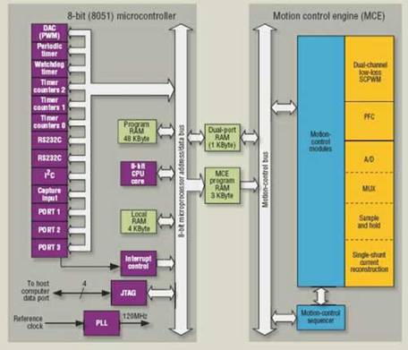
The rotor angle estimator and the current control loop consume about 1,400 system clock cycles, which is equivalent to 11μs at the maximum system clock frequency of 128MHz. In this way, the control of two motors can be achieved simultaneously with a 50μs PWM period, which is equivalent to a switching frequency of 20kHz. Of course, to control two motors, the chip needs two sets of space vector PWM modulators and additional analog inputs for current sampling. Figure 2 is a block diagram of a dual motor control IC that includes an embedded motion control engine and an 8-bit microcontroller core for executing application layer code. The advantage of this approach is that it separates the slow system-level functions executed on the microcontroller from the high-speed motor control algorithms executed by the MCE.

Figure 2: A dual motor control chip with an 8-bit microcontroller for application layer tasks
MCE Library Functions
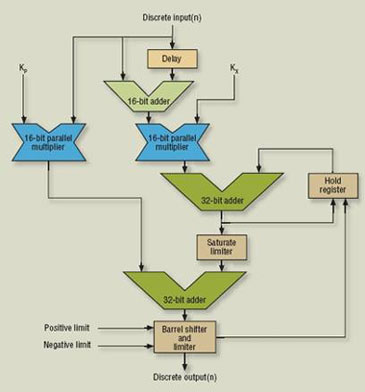
The key to high-speed execution of control algorithms is the efficiency of the MCE library functions implemented in ASICs. Two important feedback control units (PI control compensator and vector rotation block) can serve as typical examples of library functions. ASIC implementation requires optimizing the use of silicon and clock cycles without sacrificing robustness and reliability.

Figure 3: Proportional-integral (PI) control compensator efficiently uses MCE hardware resources and clock cycles
Previous article:A stepper motor control system based on motion control card
Next article:Inverter Network Control Based on Visual C++ Environment
- Popular Resources
- Popular amplifiers
- Molex leverages SAP solutions to drive smart supply chain collaboration
- Pickering Launches New Future-Proof PXIe Single-Slot Controller for High-Performance Test and Measurement Applications
- CGD and Qorvo to jointly revolutionize motor control solutions
- Advanced gameplay, Harting takes your PCB board connection to a new level!
- Nidec Intelligent Motion is the first to launch an electric clutch ECU for two-wheeled vehicles
- Bosch and Tsinghua University renew cooperation agreement on artificial intelligence research to jointly promote the development of artificial intelligence in the industrial field
- GigaDevice unveils new MCU products, deeply unlocking industrial application scenarios with diversified products and solutions
- Advantech: Investing in Edge AI Innovation to Drive an Intelligent Future
- CGD and QORVO will revolutionize motor control solutions
- Innolux's intelligent steer-by-wire solution makes cars smarter and safer
- 8051 MCU - Parity Check
- How to efficiently balance the sensitivity of tactile sensing interfaces
- What should I do if the servo motor shakes? What causes the servo motor to shake quickly?
- 【Brushless Motor】Analysis of three-phase BLDC motor and sharing of two popular development boards
- Midea Industrial Technology's subsidiaries Clou Electronics and Hekang New Energy jointly appeared at the Munich Battery Energy Storage Exhibition and Solar Energy Exhibition
- Guoxin Sichen | Application of ferroelectric memory PB85RS2MC in power battery management, with a capacity of 2M
- Analysis of common faults of frequency converter
- In a head-on competition with Qualcomm, what kind of cockpit products has Intel come up with?
- Dalian Rongke's all-vanadium liquid flow battery energy storage equipment industrialization project has entered the sprint stage before production
- Allegro MicroSystems Introduces Advanced Magnetic and Inductive Position Sensing Solutions at Electronica 2024
- Car key in the left hand, liveness detection radar in the right hand, UWB is imperative for cars!
- After a decade of rapid development, domestic CIS has entered the market
- Aegis Dagger Battery + Thor EM-i Super Hybrid, Geely New Energy has thrown out two "king bombs"
- A brief discussion on functional safety - fault, error, and failure
- In the smart car 2.0 cycle, these core industry chains are facing major opportunities!
- The United States and Japan are developing new batteries. CATL faces challenges? How should China's new energy battery industry respond?
- Murata launches high-precision 6-axis inertial sensor for automobiles
- Ford patents pre-charge alarm to help save costs and respond to emergencies
- New real-time microcontroller system from Texas Instruments enables smarter processing in automotive and industrial applications
- TI C2000 Basic Learning
- Interest group training topic: Use MOS tube or + op amp to realize a DC/DC closed-loop voltage regulator
- Simple square wave generator based on 51 single chip microcomputer
- MSP430fr6989 serial port DMA sending experimental routine
- [RISC-V MCU CH32V103 Review] First impression of CH32V103C8T6 chip
- 100 check items for PCB design to ensure you have no problems with your design!
- How to write the corresponding program process according to the timing diagram
- Differences and similarities between detection circuits, filter circuits, frequency selection circuits, threshold comparison circuits, and bandpass circuits
- When designing PCB, how to consider electromagnetic compatibility EMC/EMI, specifically...
- How to measure the PWM generated by msp430f149 with an oscilloscope

 A review of learning-based camera and lidar simulation methods for autonomous driving systems


 京公网安备 11010802033920号