I. Overview
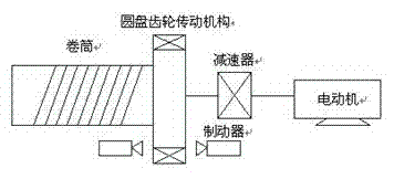
Mine hoists are important equipment in the production process of coal mines and nonferrous metal mines. The safe and reliable operation of the hoist is directly related to the production status and economic benefits of the enterprise. A coal mine in Shanxi Province mines coal underground, and the mined coal is dragged to the ground by a coal car through the inclined shaft using a hoist. This traction system requires frequent forward and reverse starting of the motor, deceleration and braking, and the speed of the motor changes regularly. The mechanical structure of the inclined shaft hoist is shown in the figure below. The power of the inclined shaft hoist is provided by a wound-rotor motor, and the speed is controlled by a rotor series resistor.

At present, most medium and small mines use inclined winch hoisting. Traditional inclined hoists generally use AC winding motor series resistance speed control system, and the switching of resistance is controlled by relay-AC contactor. Due to the frequent action of AC contactor during speed regulation, the equipment runs for a long time, and the main contact of AC contactor is easy to oxidize, causing equipment failure. In addition, the speed control performance of the hoist is poor in the deceleration and creeping stages, which often causes inaccurate parking position. Frequent starting, speed regulation and braking of the hoist generate considerable power consumption on the resistor in series with the rotor external circuit. This AC winding motor series resistance speed control system belongs to step speed regulation, and the smoothness of speed regulation is poor; the mechanical characteristics are soft at low speed, and the static difference rate is large; the slip power consumed on the resistor is large, and the energy saving is poor; the current impact is large during the starting process and speed regulation and shifting process; the vibration is large during medium and high speed operation, and the safety is poor.
2. Renovation Plan
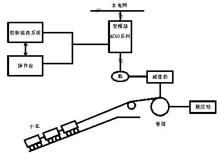
In order to overcome the shortcomings of the traditional AC winding motor series resistance speed control system, the variable frequency speed control technology is used to transform the hoist, which can achieve constant torque control in the full frequency range (0-50Hz). For the treatment of regenerative energy, a low-cost energy-consuming braking solution or a more energy-saving feedback braking solution can be used. For safety considerations, hydraulic mechanical braking needs to be retained, and hydraulic mechanical braking and inverter braking are integrated during the design process. The variable frequency speed control method of the mine hoist is shown in the figure below:

A wound-rotor motor is used on site. When driven by a frequency converter, the three lead wires of the rotor need to be short-circuited.
3. Implementation of the Program
Inclined shaft hoisting load is a typical friction load, that is, a constant torque characteristic load. When the heavy vehicle goes up, the electromagnetic torque of the motor must overcome the load resistance torque, and when starting, it must also overcome a certain static friction torque. The motor is in an electric working state and works in the first quadrant. When the heavy vehicle decelerates, although the heavy vehicle has a downward component force on the inclined shaft surface, the deceleration time of the heavy vehicle is short, and the motor will still be in a regenerative state and work in the second quadrant. When another train of heavy vehicles goes up, the motor is in a reverse electric state and works in the third and fourth quadrants. In addition, when tools or equipment are transported to the well alone, which accounts for 10% of the total operating time, the motor is purely in the second or fourth quadrant. At this time, the motor is in a regenerative power generation state for a long time and needs to be effectively braked. Therefore, a braking solution of an energy-consuming braking unit plus an energy-consuming resistor is adopted.
The load characteristic of the hoist is a constant torque potential load, and the starting torque is large. When selecting the inverter, an appropriate margin should be left. Therefore, the high-performance AC60-G series inverter of VEICHI is selected. Since the motor of the hoist is in the electric state most of the time, and only regenerative energy is generated in a few times, the inverter is connected to a brake unit and a brake resistor to meet the regenerative braking of the heavy vehicle when it is descending, and to achieve a smooth descent. There is also a hydraulic mechanical brake at the wellhead, which is similar to an electromagnetic brake. This brake is used for braking when the heavy vehicle is stationary, especially when the heavy vehicle is parked on the slope of the inclined well, and a hydraulic mechanical brake must be used for braking. The hydraulic mechanical brake is controlled by the original control system and the inverter. Whether the mechanical brake is braked is controlled by the inverter frequency arrival port. When the output frequency of the inverter reaches the set value at the start, for example, 2Hz, the inverter TA, TB, and TC ports output signals, indicating that the motor torque is large enough, the hydraulic mechanical brake is turned on, and the heavy vehicle can go up; during the deceleration process, when the frequency of the inverter drops to 2Hz, it means that the motor torque is small, and the hydraulic mechanical brake is braked to stop. In case of emergency, press the emergency stop button, the inverter will stop freely, and the hydraulic mechanical brake will work immediately to stop the hoist in the shortest possible time.
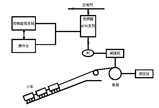
The traditional way of operating the hoist is that the operator sits in front of the operating table at the coal mine entrance and controls the motor's forward and reverse speeds with the joystick. To adapt to this operation mode of the operator, the inverter adopts multi-speed settings, with FWD and REV set to forward and reverse, and X1, X2, and X3 set to low, medium, and high speeds. The principle diagram of frequency conversion speed regulation is shown in the figure below.

The inverter settings are as follows: E-01: 1; E-02: 0; E-13: 40; E-14: 40; E-18: 6; E-23: 100; E-28: 2.00; E-33: 2.00; F-01: 5; F-02: 6; F-03: 7; F-09: 10.0; F-10: 30.0; F-12: 50.0; other settings are based on site requirements. For the above settings, please refer to the AC60 series manual.
4. Working process of hoist
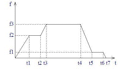
After the hoist was modified with variable frequency speed regulation, the working process of the system did not change much. The joystick controls the motor's three-speed forward rotation and three-speed reverse rotation. Regardless of whether the motor is forward or reverse, it is used to drag coal from the mine to the ground. The motor works in the forward and reverse electric states. Only when the fully loaded trailer is approaching the wellhead, it needs to slow down and brake. The working sequence diagram of the hoist is shown in Figure 4.

The working process of the hoist is the same whether it is forward or reverse, and there are seven stages: starting, acceleration, medium-speed operation, stable operation, deceleration, low-speed operation, and braking. The time of each lifting operation is related to the operating speed, acceleration and depth of the inclined shaft of the system. The magnitude of each section of acceleration is determined according to the process conditions, and the operating time is determined by the operator according to the conditions on site. The working conditions of each stage in the figure are explained as follows:
(1) The first stage 0-t1: After the train car is filled with coal at the working face at the bottom of the well, a contact signal is sent to the operator of the wellhead hoist. The operator replies with a signal to the bottom of the well and then starts the hoist. The loaded car starts to move upward from the bottom of the well, and the empty car starts to move downward at the wellhead parking lot at the same time.
(2) The second stage t1~t2: After the heavy vehicle starts, it accelerates to the frequency of the inverter and runs at speed f2. The medium-speed operation time is short and is only a transition period. If there is no problem with the equipment during the acceleration time, it will immediately accelerate to the normal operating speed.
(3) The third stage t2-t3: re-acceleration stage.
(4) The fourth stage t3-t4: The heavy vehicle runs stably at the maximum speed of the inverter frequency f3. Generally, this process is the longest.
(5) The fifth stage t4-t5: When the operator sees that the heavy vehicle is approaching the wellhead, he immediately decelerates. If the deceleration time is set to a short time, the inverter braking unit and braking resistor will work and the circuit breaker will not trip due to excessive deceleration.
(6) The sixth stage t5-t6: The heavy vehicle decelerates to a low speed and crawls at a low speed with the inverter frequency f1 to facilitate parking at the specified position.
(7) The seventh stage t6-t7: When approaching the parking position, the inverter stops immediately, the heavy vehicle decelerates to zero, and the operator sends a contact signal to the underground, and the entire lifting process ends.
The above is a manual operation procedure, and you can also work according to the automatic operation procedure of the operating console.
The acceleration and deceleration times in the figure are set on the inverter.
V. Conclusion
The winding motor rotor is connected to a resistor in series with the speed regulator, and a large amount of slip power is consumed on the resistor. The lower the speed, the greater the slip power consumed. Using variable frequency speed regulation is an energy-saving and efficient speed regulation method. The hoist is in electric state most of the time, which saves energy significantly. It has been calculated that the energy saving is more than 30%, and a good economic benefit has been achieved. In addition, after the hoist is variable frequency speed regulated, the stability and safety of the system operation are greatly improved, the operation failures and downtime maintenance hours are reduced, manpower and material resources are saved, the coal transportation capacity is improved, and the indirect economic benefits are also considerable.
Previous article:180° motor control and home appliance fan solutions
Next article:Application research of Simotion D in foundation cover equipment
- Popular Resources
- Popular amplifiers
- Molex leverages SAP solutions to drive smart supply chain collaboration
- Pickering Launches New Future-Proof PXIe Single-Slot Controller for High-Performance Test and Measurement Applications
- CGD and Qorvo to jointly revolutionize motor control solutions
- Advanced gameplay, Harting takes your PCB board connection to a new level!
- Nidec Intelligent Motion is the first to launch an electric clutch ECU for two-wheeled vehicles
- Bosch and Tsinghua University renew cooperation agreement on artificial intelligence research to jointly promote the development of artificial intelligence in the industrial field
- GigaDevice unveils new MCU products, deeply unlocking industrial application scenarios with diversified products and solutions
- Advantech: Investing in Edge AI Innovation to Drive an Intelligent Future
- CGD and QORVO will revolutionize motor control solutions
- Innolux's intelligent steer-by-wire solution makes cars smarter and safer
- 8051 MCU - Parity Check
- How to efficiently balance the sensitivity of tactile sensing interfaces
- What should I do if the servo motor shakes? What causes the servo motor to shake quickly?
- 【Brushless Motor】Analysis of three-phase BLDC motor and sharing of two popular development boards
- Midea Industrial Technology's subsidiaries Clou Electronics and Hekang New Energy jointly appeared at the Munich Battery Energy Storage Exhibition and Solar Energy Exhibition
- Guoxin Sichen | Application of ferroelectric memory PB85RS2MC in power battery management, with a capacity of 2M
- Analysis of common faults of frequency converter
- In a head-on competition with Qualcomm, what kind of cockpit products has Intel come up with?
- Dalian Rongke's all-vanadium liquid flow battery energy storage equipment industrialization project has entered the sprint stage before production
- Allegro MicroSystems Introduces Advanced Magnetic and Inductive Position Sensing Solutions at Electronica 2024
- Car key in the left hand, liveness detection radar in the right hand, UWB is imperative for cars!
- After a decade of rapid development, domestic CIS has entered the market
- Aegis Dagger Battery + Thor EM-i Super Hybrid, Geely New Energy has thrown out two "king bombs"
- A brief discussion on functional safety - fault, error, and failure
- In the smart car 2.0 cycle, these core industry chains are facing major opportunities!
- The United States and Japan are developing new batteries. CATL faces challenges? How should China's new energy battery industry respond?
- Murata launches high-precision 6-axis inertial sensor for automobiles
- Ford patents pre-charge alarm to help save costs and respond to emergencies
- New real-time microcontroller system from Texas Instruments enables smarter processing in automotive and industrial applications
- MSP430 standby power consumption problem
- How feasible is it for the United States to skip 5G and go directly to 6G?
- [TI recommended course] #TI? Application of interface chips in automotive products#
- 【Gravity:AS7341 Review】+Bought some colored paper for testing
- 008
- Showing Goods (7) - Open Source Development Board
- New version of IAR installation problems and solutions
- Disassembling I-Mu/Huanxiang Huanxiang Yangmeituqi Bluetooth Speaker
- arm assembly instructions WFI and WFE
- CCS new project and library file loading

 A review of learning-based camera and lidar simulation methods for autonomous driving systems
 Visual ModelQ V7


 京公网安备 11010802033920号