Temperature Sensors Things have changed a lot now, and until now, all temperature sensors available on the market did not have analog/digital output capabilities. The use of thermistors, RTDs, and thermocouples is accompanied by the use of an analog conversion device or silicon temperature sensor. Unfortunately, in important applications, these analog output devices require a comparator, an ADC, or an amplifier to convert their analog signals into useful signals.
Therefore, when the integration capability reaches a higher level, temperature sensors with digital interfaces can appear. There are many varieties of Ics temperature sensors currently sold, from simple devices that handle over-limit temperature signals to remote temperature control and measurement, and can perform scientific temperature programming. The current choice is not just the selection of analog output or digital output sensor functions, but also a wider selection of sensor models, and all these choices should be matched with your system as the principle.
Types of Temperature Sensors
Now four temperature sensors are shown in Figure 1. Ideally, an analog sensor provides an output voltage that has an extremely linear function of temperature. Sensor B is a digital I/O type that amplifies the 1 and 0 temperature digital signals to a microprocessor via a serial bus. Along the same bus, data can also be transmitted from the microprocessor to the temperature sensor, usually to set a digital temperature output alarm. When the temperature reaches the limit, an alarm interrupt signal is transmitted to the microcontroller. This type of sensor can be used for fan control.
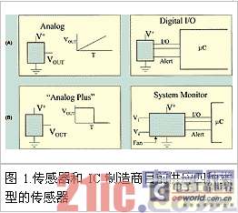
"Analog pulse" sensors (C) can have various forms of digital output. The curve of voltage VVOUT vs. temperature is determined by the IC, and its digital output changes when a particular temperature limit is exceeded. In this case, the "pulse" is applied to the analog temperature sensor, and no comparator and reference voltage are required. Other types of "pulse" components transmit temperature data in the form of a delay time when the device is enabled, and may also be in the form of a frequency or square wave (to be discussed later).
The system monitoring type (D) is the most complex type of the four. It can be used in conjunction with a digital I/O port. This type of device is generally used to detect system voltage and provide an alarm signal when the voltage rises or drops to a certain I/O setting value.
Fan monitoring and/or control is sometimes done using this type of IC. In some cases, this device is used to determine if a fan is functioning properly. More complex models can be used to control a fan with one or more temperature measurement points. System monitoring sensors are not discussed here because they involve giving a complex function model that can be used with temperature sensors.
Analog Output Temperature Sensors
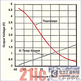
Both thermistors and silicon temperature sensors are widely used as analog output temperature sensors. Figure 2 clearly shows the linear relationship between voltage and temperature. The linearity of silicon temperature sensors is much better than that of thermistors. However, within a narrow temperature range, thermistors also provide reasonable linearity and good sensitivity. Many early circuits built with thermistors are now obsolete and have been replaced by silicon temperature sensors.
Silicon temperature sensors can use different scale output forms, for example, in output conversion it can be expressed in K, 0C and 0F.
In most applications, the output of these devices is fed into a comparator or A/D converter to convert the temperature data into a digital format. Although this is an additional requirement for the device, thermistors and silicon temperature sensors have been used for many years due to their low cost.
[page]
Temperature Sensor with Digital I/O Interface
About five years ago, a new type of temperature sensor was introduced. These devices include a digital interface (which allows communication with a microcontroller). This communication interface commonly includes I2C and SMBus serial buses, but other serial communication interfaces (such as SPI) are also common. The interface can transmit digital data to the microprocessor, and the interface can also receive commands from the microcontroller. These commands are often temperature thresholds, that is, if the temperature exceeds the limit, a digital signal will be generated on the temperature sensor IC (which will generate an interrupt to the microcontroller). The microcontroller can then adjust the fan speed or adjust the microprocessor to keep the temperature under control.
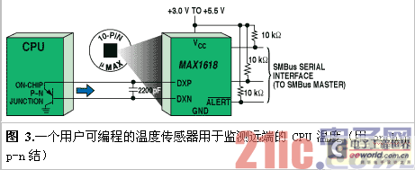
Such devices are widely used in applications where remote temperature measurements can be made. To perform remote measurements, most high-performance CPUs include an on-chip converter that provides an analog voltage value for the temperature. (Only one of the converter's two pn junctions is used.) Figure 3 shows a monitored telemetry CPU using this technology. Another application uses a discrete converter to perform the same function.
Another important feature of this type of sensor (including the sensor shown in Figure 3) is the ability to interrupt the microprocessor when the measured temperature is not within the range between the upper and lower limits. In other sensors, an interrupt signal should be generated when the measured temperature value crosses the upper or lower limit (not both values at the same time). For the sensor in Figure 3, these threshold values are transmitted to the temperature sensor through the SMBus interface. If the temperature changes outside the threshold value range, the alarm signal should be able to interrupt the microprocessor.
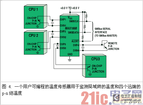
Figure 4 shows a similar device, however, instead of monitoring one pn junction, it monitors four junctions and its own internal temperature. Because Maxim's MAX1668 consumes very little power, its internal temperature is close to the ambient temperature. Measuring the ambient temperature can determine whether the system fan is operating properly.
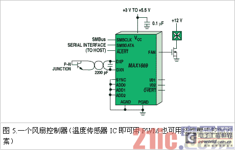
Controlling a fan by remotely monitoring temperature is the main function of the IC shown in Figure 5. In this case the user can choose between two different modes of fan control. With PWM mode, the microprocessor controls the fan speed as a function of the measured temperature by varying the period of the signal sent to the fan. This requires far less power than would be produced by the linear mode of the control. Since some fans emit an audible sound when the PWM signal frequency is controlled, the linear mode has advantages in this regard, but there is a high power consumption and the need for other additional circuits, although the additional power consumption is only a small part of the total system power consumption.
When the temperature exceeds the specified threshold, the IC provides an alarm signal that interrupts the microprocessor. A safety mode with an obvious signal (a short-term over-temperature signal) is also provided. When the temperature rises to a dangerous value, if the microprocessor or software does not operate normally, the alarm signal will lose its meaning. However, it is obvious that once the temperature rises to a certain set value (via SMBus), it will act on the control circuit without the help of the microprocessor. Therefore, at this high temperature, the most obvious way for the microprocessor should be to directly shut down the power supply without microprocessor control to prevent potential catastrophic failures.
The device's digital I/O can be widely used in servers, battery packs and hard disk drives. Numerous temperature points can be used to monitor numerous measurement points to increase server reliability. On the motherboard (it is the basic ambient temperature on the chassis), inside the CPU, in other heat-generating components (such as graphics accelerators and hard disk drives). For safety reasons, the battery pack incorporates temperature sensors and optimized battery shape, which can increase the battery life.
[page]
There are two good ways to monitor the temperature of a hard drive, relying on the initial speed of the motor and the ambient temperature. Errors in the readings of the drive increase the error range of the temperature. The MTBF of a hard drive is generally improved by controlling the temperature. By measuring the temperature within the system, you can control the motor speed to optimize the reliability of the system. The drive can be shut down. In systems where high reliability is required, alarms can be generated for the management system to indicate temperature thresholds or possible data loss.
Analog pulse sensor
"Analog pulse" sensors are generally suitable for simpler measurement applications. These ICs can generate a logic output converted from the measured temperature to a microprocessor. The main difference between digital I/O sensors is that they have bidirectional transmission capabilities.
In the simplest example of an analog pulse sensor, a logic output pulse is triggered when a specific temperature exceeds a limit. Parts of these devices are triggered when the temperature rises above a specified limit or falls below a specified limit. This type of sensor allows the temperature threshold to be adjusted along with the resistance value while the other parts have a fixed threshold.
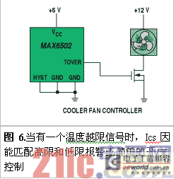
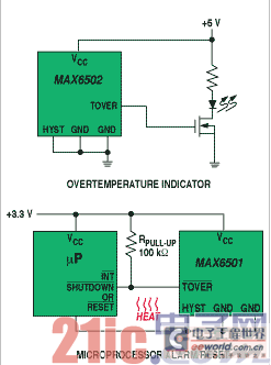
A particular internal temperature threshold is used in the application shown in Figure 6. Three circuits are shown for this application with a common use: alarm, equipment shutdown, or fan operation.
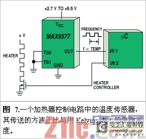
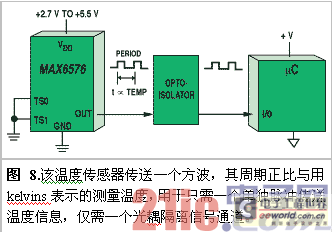
When an actual temperature reading is required, a microprocessor can be used, along with a sensor that transmits a single signal. The signal from such a temperature sensor can be easily converted to a measured temperature by measuring the time with a counter inside the microprocessor. The sensor in Figure 7 outputs a square wave whose frequency is proportional to the ambient temperature (Kelvin). The device in Figure 8 is similar, but the period of the square wave is proportional to the ambient temperature (Kelvin).
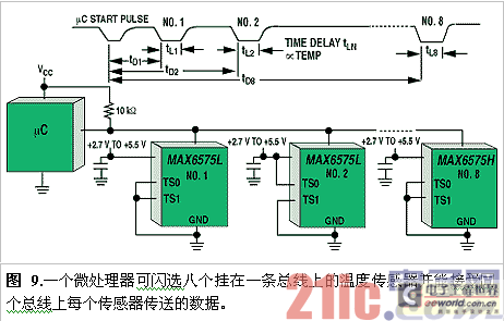
Figure 9 shows a practical application that allows eight temperature sensors to be connected to the same bus. When the microprocessor's I/O port selects the sensors on the bus at the same time, the process of reading the temperature from these temperature sensors begins. In order to receive data from each sensor, the microprocessor quickly deploys the interface to meet the input conditions. After the sensor is selected, the microprocessor decodes the read data. Each sensor is decoded when the strobe pulse arrives within a specific range of time. By allocating a time range for each sensor to transmit data, decoding conflicts can be avoided.
The accuracy achieved by this method is surprisingly high: 0.80°C at room temperature, which matches exactly the temperature data transmitted by the IC in the form of a square wave frequency. The same situation also applies to the period of the square wave.
This device is particularly effective in applications where wires are limited. For example, when the temperature sensor should be isolated from the microprocessor, the cost can be kept very low because only an optocoupler is needed. In automation and HVAC applications, these sensors are also particularly suitable because the distance makes them use less copper.
Outlook on the development of temperature sensors
IC sensors can provide a combination of various functional interfaces. As these devices continue to improve, system setters will see more application effects - new features and new ways for sensors to display special interfaces in the system. Eventually, the chip design level will reach the level of integrating more electronic components on a chip to ensure that the temperature sensor can contain more new functions and more special interfaces.
Previous article:Principle and Application of Digital Temperature Sensor DS1722
Next article:The use of infrared transmitting tubes and the issues of emission angle and intensity
- Popular Resources
- Popular amplifiers
- Molex leverages SAP solutions to drive smart supply chain collaboration
- Pickering Launches New Future-Proof PXIe Single-Slot Controller for High-Performance Test and Measurement Applications
- CGD and Qorvo to jointly revolutionize motor control solutions
- Advanced gameplay, Harting takes your PCB board connection to a new level!
- Nidec Intelligent Motion is the first to launch an electric clutch ECU for two-wheeled vehicles
- Bosch and Tsinghua University renew cooperation agreement on artificial intelligence research to jointly promote the development of artificial intelligence in the industrial field
- GigaDevice unveils new MCU products, deeply unlocking industrial application scenarios with diversified products and solutions
- Advantech: Investing in Edge AI Innovation to Drive an Intelligent Future
- CGD and QORVO will revolutionize motor control solutions
- Innolux's intelligent steer-by-wire solution makes cars smarter and safer
- 8051 MCU - Parity Check
- How to efficiently balance the sensitivity of tactile sensing interfaces
- What should I do if the servo motor shakes? What causes the servo motor to shake quickly?
- 【Brushless Motor】Analysis of three-phase BLDC motor and sharing of two popular development boards
- Midea Industrial Technology's subsidiaries Clou Electronics and Hekang New Energy jointly appeared at the Munich Battery Energy Storage Exhibition and Solar Energy Exhibition
- Guoxin Sichen | Application of ferroelectric memory PB85RS2MC in power battery management, with a capacity of 2M
- Analysis of common faults of frequency converter
- In a head-on competition with Qualcomm, what kind of cockpit products has Intel come up with?
- Dalian Rongke's all-vanadium liquid flow battery energy storage equipment industrialization project has entered the sprint stage before production
- Allegro MicroSystems Introduces Advanced Magnetic and Inductive Position Sensing Solutions at Electronica 2024
- Car key in the left hand, liveness detection radar in the right hand, UWB is imperative for cars!
- After a decade of rapid development, domestic CIS has entered the market
- Aegis Dagger Battery + Thor EM-i Super Hybrid, Geely New Energy has thrown out two "king bombs"
- A brief discussion on functional safety - fault, error, and failure
- In the smart car 2.0 cycle, these core industry chains are facing major opportunities!
- The United States and Japan are developing new batteries. CATL faces challenges? How should China's new energy battery industry respond?
- Murata launches high-precision 6-axis inertial sensor for automobiles
- Ford patents pre-charge alarm to help save costs and respond to emergencies
- New real-time microcontroller system from Texas Instruments enables smarter processing in automotive and industrial applications
- ODROID-GO handheld game console emulator based on ESP32
- [Liquid Level Sensor Evaluation] Re-understanding of Capacitive-Contactless Liquid Level Sensor
- LED PWM Dimming C Program
- FPGA introductory series experimental tutorial - key debounce control LED on and off
- Crazy Shell AI open source drone flight control machine code reading, compilation and burning
- TWS Headphones ANC Design Guide Basics 01
- What is c_int00 when programming DSP?
- Keil.STM32H7xx_DFP.2.2.0 installation package problem
- [Ultra-low power STM32U5 IoT Discovery Kit] - 2: wifi
- Why can't I debug CCS7.0 suddenly?

 5962-8997501PA


 京公网安备 11010802033920号