Abstract: In order to shorten the design cycle of convolutional encoder and make hardware design more flexible, based on the introduction of the convolutional encoder principle, this paper discusses a method of implementing the forward link convolutional encoder of CDMA2000 system based on programmable logic devices, using modular design method and VHDL hardware description language. The simulation results under QuartusⅡ software are given, and the implementation is verified on FPGA devices. Both simulation and experiment prove the feasibility and correctness of this method.
Keywords: FPGA; VHDL; CDMA 2000; convolutional encoder; forward error control
0 Introduction
In the communication system, since the digital signal is affected by various interferences during the transmission process, the waveform of the signal code element is deteriorated, so the error judgment may occur after transmission to the receiving end. To solve this problem, when designing a digital communication system, it is usually necessary to first consider the reasonable selection of modulation system, demodulation method and transmission power. If the above measures are still difficult to meet the requirements, error control measures should be considered. Convolutional coding is used to implement forward error control (FEC) in the forward link and reverse link of the CDMA 2000 system.
FPGA is a programmable logic device. Its main advantage is that the hardware structure and working mode of the device can be reconstructed through software programming with the help of EDA tools, which makes hardware design flexible and convenient as software design. This design uses VHDL language and selects programmable logic devices to implement the forward link convolution encoder in the CDMA 2000 system under QuartusⅡ.
1 Principle of convolution encoder
Convolutional code was first proposed by P. Elias in 1954. It is a non-block code. It is usually more suitable for forward error correction because its performance is often better than block code for many practical situations and the equipment is simple. Since A. J. Viterbi discovered an effective decoding algorithm in 1967 and J. Omura proved that this is an ML decoding algorithm in 1969, convolutional codes using Viterbi decoding algorithm have become an indispensable coding scheme in modern communication systems. CDMA 2000 system also adopts this coding scheme.
1.1 Principle of convolutional encoder
Unlike block code encoders, convolutional code encoders have memory, that is, the n code elements generated by the encoder in any period of time depend not only on the k information bits in this period of time, but also on the information bits in the previous N-1 specified periods of time; that is, the n code elements generated by the encoder are related to each k-bit information bit being shifted in. For the convenience of explanation, it is stipulated here that the coding rate r=k/n. Among them, k represents the number of information bits shifted into the encoder at one time; n represents the number of symbols output by the encoder corresponding to the k-bit information shifted in. In addition, K is used to represent the constraint length, which is equal to the number of stages of the shift register in the encoder; in fact, the first shift register is redundant.
There are many ways to describe the convolutional coding process, such as: polynomial method, matrix method, tree diagram and grid diagram. Here, the polynomial method closely related to the structure of the convolutional encoder is used to illustrate the coding principle of the convolutional code. A convolutional encoder with a coding rate of r = 1/2 and a constraint length of K = 3 is known. The generator polynomial matrix of its convolutional code is:
![]()
Where: D is the delay operator, the first term of the generator polynomial is 1+D2, indicating that the first codeword c1 output by the encoder is equal to the modulo 2 sum of the input codeword b1 and the previous input codeword b3; its second term is D+D2, indicating that the second codeword c2 output is the modulo 2 sum of the previous two input codewords b2 and b3.
The structure diagram of the encoder can be directly obtained according to the generator polynomial matrix of the convolutional code, as shown in Figure 1. In the figure, s1 and s2 are shift registers; m1 and m2 are modulo 2 sum adders; b1 represents the current input information bit; the shift register states b2 and b3 store the previous information bits; c1 and c2 represent the output codewords after encoding.
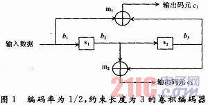
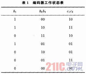
In the encoding process of the convolutional code, the encoder starts from the all-zero state and must return to the all-zero state in the end. Therefore, after sending the information, K-1 segments of all-zero information must be sent to the encoder to force the encoder to return to the all-zero state. Assume that the initial state of this encoder is zero, that is, b1b2b3 is 000. When the input information bit is 11010, in order to ensure that all the input information bits can pass through the shift register and reset the shift register, the constraint length minus one zero must be added after the information bit, that is, two zeros; the corresponding output code element sequence is: 10111001011100, and the output information of the encoder can be obtained by discarding the last four bits: 1011100101. The state of the encoder during the entire working process is shown in Table 1.
1.2 Convolutional encoder for the forward link in the CDMA 2000 system
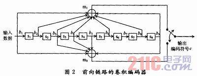
In the CDMA 2000 system, the forward link uses a convolutional encoder with a coding rate of 1/2 and a constraint length of 9. The generator polynomial matrix of the forward link convolutional code is:

The structure diagram of the forward encoder can be obtained from the generator polynomial matrix, as shown in Figure 2. In the figure, s1~s8 are shift registers; m1 and m2 are modulo 2 and adders; b1 represents the current input information bit; shift register states b2~b9 store the previous information bits; c represents the output codeword after encoding.
2 Implementation of the forward link convolutional encoder in the CDMA 2000 system
2.1 Circuit composition of the forward link convolutional encoder in the CDMA 2000 system
This design adopts a modular design method. According to the function of the forward link convolutional encoder in the CDMA2000 system, its internal structure is divided into four modules: shift register group, modulo 2 and adder, output controller and clock circuit. Each module corresponds to a part of the VHDL design file, which is conducive to program writing and debugging, thereby reducing the difficulty of debugging the entire program and improving the maintainability and readability of the software. The block diagram of the forward link convolutional encoder is shown in Figure 3.
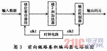
Among them, the clock signals clk1 and clk2 can be directly provided by the clock circuit of the base station controller (BSC), or the clock circuit designed in this paper can divide the original clock signal provided by the base station controller (BSC) by frequency division; the output controller includes two parts: output data synthesis circuit and shaping circuit.
2.2 Simulation and implementation of CDMA 2000 forward link convolution encoder
According to the convolution encoder circuit block diagram, the source program of the forward link convolution encoder is written in VHDL language and input into QuartusⅡ development software for compilation, simulation and synthesis to obtain a downloadable file, and then the design is completed by programming the device.
Before simulation, it is assumed that the initial state of the encoder is zero, that is, b1~b9 is 00000000; the input information is 11010. To ensure that all the input information bits can pass through the shift register and reset the shift register, 8 zeros are added after the information bit. The output result is 11010111000001111111101100. During simulation, the input data rate is 9.6Kb/s; the output code c rate is 19.2Kb/s. The simulation results are shown in Figure 4, where b is the state of the register group at each moment.
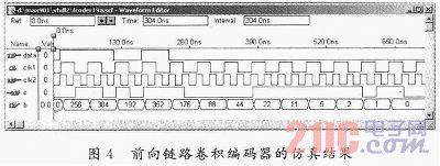
There are some issues that need to be noted in the design of the forward link convolution encoder: First of all, it should be clear that VHDL language is different from other computer languages. It is a hardware description language, and the object it describes is an objective circuit system. Secondly, different EDA tools support VHDL language to different degrees. The QuartusⅡ development tool used in this design is mainly software for programmable logic devices. It does not support all VHDL statements. It only supports RTL-level descriptions, not behavioral-level descriptions. In addition, in the design, it is necessary to make reasonable choices based on the design requirements and the resource conditions and speed of the programmable logic device. The EP2C8Q208 device used in this design can meet the requirements in terms of resources and speed.
3 Conclusion
This paper implements a forward link convolution encoder suitable for CDMA 2000 system. Through the design, simulation and commissioning of the overall circuit, the results show that this encoder can meet the requirements of CDMA 2000 system and has certain practical value. At the same time, this design adopts the idea of designing based on programmable logic devices with the help of VHDL language and EDA tools, which greatly shortens the design cycle, reduces costs, improves the reliability and flexibility of the design, and provides an effective design method for communication system design.
Previous article:An Implementation of uIP TCP/IP Protocol Stack on 51 Series MCU
Next article:1.2 to 33 VDC digital voltage supply design
- Popular Resources
- Popular amplifiers
- Molex leverages SAP solutions to drive smart supply chain collaboration
- Pickering Launches New Future-Proof PXIe Single-Slot Controller for High-Performance Test and Measurement Applications
- CGD and Qorvo to jointly revolutionize motor control solutions
- Advanced gameplay, Harting takes your PCB board connection to a new level!
- Nidec Intelligent Motion is the first to launch an electric clutch ECU for two-wheeled vehicles
- Bosch and Tsinghua University renew cooperation agreement on artificial intelligence research to jointly promote the development of artificial intelligence in the industrial field
- GigaDevice unveils new MCU products, deeply unlocking industrial application scenarios with diversified products and solutions
- Advantech: Investing in Edge AI Innovation to Drive an Intelligent Future
- CGD and QORVO will revolutionize motor control solutions
- Innolux's intelligent steer-by-wire solution makes cars smarter and safer
- 8051 MCU - Parity Check
- How to efficiently balance the sensitivity of tactile sensing interfaces
- What should I do if the servo motor shakes? What causes the servo motor to shake quickly?
- 【Brushless Motor】Analysis of three-phase BLDC motor and sharing of two popular development boards
- Midea Industrial Technology's subsidiaries Clou Electronics and Hekang New Energy jointly appeared at the Munich Battery Energy Storage Exhibition and Solar Energy Exhibition
- Guoxin Sichen | Application of ferroelectric memory PB85RS2MC in power battery management, with a capacity of 2M
- Analysis of common faults of frequency converter
- In a head-on competition with Qualcomm, what kind of cockpit products has Intel come up with?
- Dalian Rongke's all-vanadium liquid flow battery energy storage equipment industrialization project has entered the sprint stage before production
- Allegro MicroSystems Introduces Advanced Magnetic and Inductive Position Sensing Solutions at Electronica 2024
- Car key in the left hand, liveness detection radar in the right hand, UWB is imperative for cars!
- After a decade of rapid development, domestic CIS has entered the market
- Aegis Dagger Battery + Thor EM-i Super Hybrid, Geely New Energy has thrown out two "king bombs"
- A brief discussion on functional safety - fault, error, and failure
- In the smart car 2.0 cycle, these core industry chains are facing major opportunities!
- The United States and Japan are developing new batteries. CATL faces challenges? How should China's new energy battery industry respond?
- Murata launches high-precision 6-axis inertial sensor for automobiles
- Ford patents pre-charge alarm to help save costs and respond to emergencies
- New real-time microcontroller system from Texas Instruments enables smarter processing in automotive and industrial applications
- kicad-age_12-layer_ciaa_acc
- Goodbye 2019, Hello 2020 + Standing at the Crossroads of Life
- 【GD32307E-START】02-Drawing of mechanical dimension drawings
- Xunwei i.MX6ULL Terminator Buildoot file system construction chapter buildroot file system test
- Spectrum Analysis Series: Why do we need a preselector?
- NXP LPC824
- Servo System, edited by Zeng Lesheng and Shi Miaohe, complete version with cover.pdf
- Evaluation Weekly Report 20220808: The highest performance MCU of Jihai M3 is here, another domestic FPGA is here, and the 999 yuan kit is free~
- Digital tube information
- How can I learn mmwave's xwr18xx? Can I ask for help from the forum masters? I just glanced at the SDK user guide...

 LM11CLN/A+


 京公网安备 11010802033920号