With the rapid development of modern power electronics technology, a large number of nonlinear loads have been added to the power grid, such as the widespread application of large-capacity current conversion equipment, frequency conversion equipment, switching power supplies, etc., resulting in the generation of a large number of harmonics. These harmonics distort the voltage and current waveforms of the power grid, causing the power quality to decline.
Active power filters (APFs) can effectively suppress harmonics and current distortion in improving power quality. APFs also have the advantages of good adaptability to power grid impedance and harmonic frequency, real-time compensation of harmonics, and timely compensation of reactive power.
Active power filters are mainly used to suppress and compensate harmonics in the power grid. The key to accurate and timely compensation of harmonics by APF is to quickly, accurately and timely obtain the harmonic signal of the load current through a certain detection method, and then generate compensation signals to offset the harmonics in the power supply to achieve the purpose of harmonic compensation. Because the essence of the APF harmonic detection method is to extract the fundamental wave through a certain method to detect the purpose of harmonics, the key to the harmonic detection method of the active power filter is to extract the fundamental wave component. This paper studies the most critical fundamental wave extraction part in the harmonic detection method, that is, the traditional pi-qi method, the average value method and the positive sequence fundamental wave extraction method. This paper first studies the theory and then compares and analyzes the three methods from the perspective of simulation based on the theory.
2 Basic principles of three fundamental wave extraction methods
2.1 Traditional ip-iq method based on instantaneous reactive power theory
The block diagram of the working principle of the traditional pi-qi method based on instantaneous reactive power theory is shown in Figure 1. First, assume that the instantaneous values of the voltage and current of each phase of the three-phase circuit are ea, eb, ec and ia, ib, ic, respectively. They are transformed by 32C to obtain the two-phase instantaneous voltage ea, eβ and two-phase instantaneous current ia, iβ in the a, β orthogonal coordinate system. After the a-phase grid voltage ea passes through a phase-locked loop (PLL) and a sine and cosine signal generating circuit, the sine signal sinwt and the corresponding cosine signal -coswt with the same phase as ae are obtained. These two signals are transformed by C32 to obtain ea, eβ and ia, iβ together to calculate ip, iq. IP, iq are passed through a low-pass filter (LPF) to obtain ip, iq DC components
 , and then the fundamental wave components iaf, ibf, icf can be obtained by inverse transformation; since
 is generated by iaf, ibf, icf, it is
 obtained by After transformation by C-1 and C23, the fundamental components iaf, ibf and icf of the three-phase current can be obtained. The harmonic components iah, ibh and ich of the three-phase current can be obtained by subtracting the fundamental current from the power supply current ia, ib and ic.
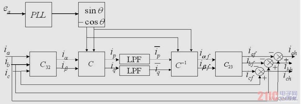
Figure 1 Schematic diagram of traditional IP-IQ method
in:

2.2 Average value method based on instantaneous reactive power theory
The average value method uses the current average value principle and is an improved fundamental wave extraction method based on the instantaneous reactive power theory compared to the traditional pi-qi method. The most critical part of this method is to extract the DC component and separate the DC quantity corresponding to the fundamental wave component using the module established by the average value principle, and then propose the corresponding fundamental wave component. The block diagram of the average value module is shown in Figure 2. The block diagram includes integration, delay, subtraction and gain modules, where T is the power supply period, and the output of the delay module is the value of the current integration delay T/6.
The entire working principle block diagram of this method is different from the traditional ip-iq method in that the LPF is replaced by a module as shown in Figure 2.
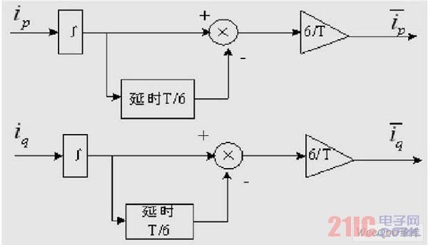
Figure 2 Block diagram of the integral delay gain link in the average value method
The symmetrical three-phase load current is transformed by Fourier decomposition into the following formula:
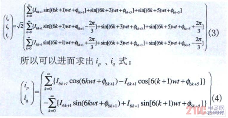
From the above formula, we can see that in addition to the DC component, the period of the AC component in ip and iq is 1/6 of the power supply period, that is, the average value of the AC component in 1/6 of the power supply period is 0. Therefore, the DC components ip and iq of ip and iq can be obtained through the average value algorithm. The average value module formula algorithm is as follows:

2.3 Positive Sequence Method
The whole principle block diagram of the positive sequence method is shown in Figure 3. This method only uses a positive sequence fundamental wave extractor module to replace the LPF, PLL and coordinate transformation in the traditional ip-iq method. The basic principle of the positive sequence fundamental wave extractor is to transform the input signal source through Laplace transformation to obtain expression (6). When the input signal source contains other harmonic components in addition to the fundamental component, the amplitude integral signal of the fundamental frequency sinusoidal signal can be obtained by the operation of equation (6), so the operation of this equation has frequency selectivity.


Figure 3 Principle diagram of positive sequence method
The positive sequence fundamental wave extractor module in the block diagram is shown in FIG4 , where K is a proportionality coefficient.
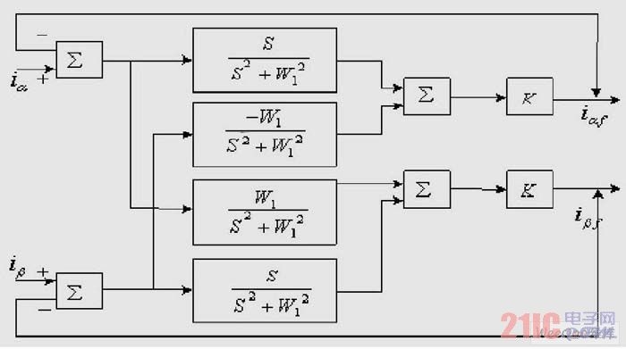
Figure 4 Module diagram of positive sequence fundamental wave extractor
3. Establishment of simulation model
The principles and algorithms of the above three fundamental wave extraction methods are the basis for establishing the simulation model. First, design the three-phase/two-phase transformation matrix simulation module as shown in Figure 5, that is, select adders and etc. in the common module library of Simulink, or you can choose the M function module to build the transformation. Here, the simpler former is selected to build the simulation model.
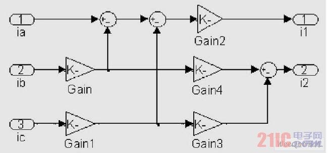
Figure 5 Three-phase/two-phase conversion
The power input module is divided into three-phase symmetrical power supply and distorted asymmetric power supply, and the load is divided into symmetrical and asymmetric full-controlled rectifier bridge. Here, the signal source modeling when the power supply has distorted three-phase asymmetric load is given as shown in Figure 6.
[page]
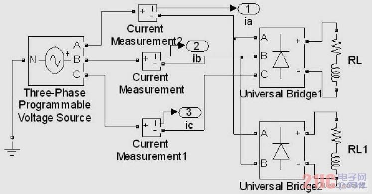
Figure 6 Signal model when the power supply has distorted asymmetric load
Table 1 Power supply voltage, resistance and other parameters.
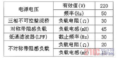
The entire simulation model of the three fundamental wave extraction methods can be established by the above submodules and the above principle block diagram. The average value module can be composed of the integrator, fixed time delay and signal gain modules in the continuous system module library. The positive sequence fundamental wave module can establish the entire simulation model using the integral module in the Simulink tool according to the above principle diagram.
The parameters of the power supply voltage, load, and LPF are shown in Table 1.
4 Simulation results and comparison
4.1 Simulation results
Based on the simulation models of the above three fundamental wave extraction methods and the parameters set in Table 1, this paper considers the simulation of the two cases of undistorted three-phase symmetrical load and distorted three-phase asymmetrical load, and the waveforms of various currents in phase A are as follows. Figure 7 shows the grid current and the fundamental wave current obtained by various methods when the power supply is undistorted and symmetrically loaded.
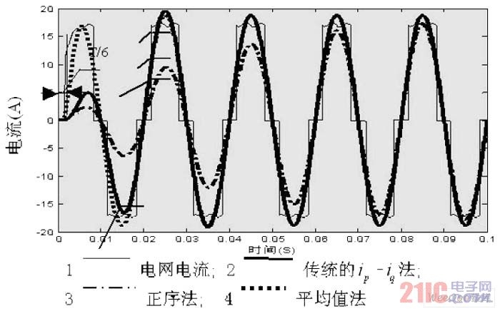
Figure 7 A-phase grid current and fundamental current when the power supply is undistorted and symmetrically loaded
From Figure 7 above, we know that the fundamental current waveform obtained by the positive sequence method tends to be stable after two cycles, and the fundamental separated in the first two cycles is not complete; the fundamental obtained by the traditional ip-iq method begins to tend to be stable and close to a sine wave after one cycle; the fundamental waveform obtained by the average method tends to be a sine waveform in the first cycle, which increases the entire delay to 1/6 of the power cycle, and the fundamental waveforms obtained by the three methods completely overlap after two cycles. This simulation test diagram strongly verifies the effectiveness and feasibility of the three methods in extracting fundamentals under the condition of symmetrical load and no distortion.
The simulation waveform in Figure 8 is the waveform of the separated fundamental current with the addition of the 5th zero-sequence and 7th negative-sequence harmonic currents of a certain amplitude to the power supply voltage, as well as the grid current under asymmetrical load. The figure shows that both the traditional ip-iq method and the positive sequence method can effectively separate the fundamental wave. After two cycles, the fundamental waves of the two methods are completely close to the sine wave and overlap, and the positive sequence method is more accurate in extraction. Although the average value method has better real-time performance in this case, it is worse than the symmetrical case. Due to the distortion of the power grid, the entire delay is increased to close to 1/6 of the power supply cycle, that is, slightly greater than T/6, but the fundamental wave extraction is not thorough, the waveform is not close to the sine wave and even contains a small amount of distortion.
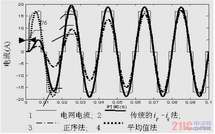
Figure 8 Phase A grid current and fundamental current when the power supply has distorted asymmetric load
4.2 Comparative Analysis
Comparing and analyzing the principles of the three methods, the difference between the average value method and the traditional ip-iq method is that the LPF in the traditional ip-iq method is replaced by the average value module. The average value module makes the filtering algorithm simpler while achieving the same filtering effect. The difference between the positive sequence method and the above two methods is that the positive sequence fundamental wave module is used to replace the LPF in the traditional ip-iq method, and the average value mathematical module is not used. This method aims at some defects of the fundamental wave extraction method based on instantaneous reactive power theory, that is, the current fundamental wave extraction method based on instantaneous reactive power theory has complex filtering control algorithms and incomplete reactive component filtering. Therefore, a method based on positive sequence fundamental wave extraction is used to make up for these shortcomings. The positive sequence method has the advantages of being insensitive to grid fundamental frequency deviation and accurate extraction of positive sequence fundamental wave signals.
Comparing and analyzing the simulation waveforms of the three methods, the average value method does increase the entire delay to 1/6 of the power supply cycle. The fundamental wave delay extracted by the positive sequence method is slightly larger and tends to be stable after two power supply cycles. However, it can still accurately and effectively extract the fundamental wave current with high accuracy when the power supply has distorted three-phase asymmetric load.
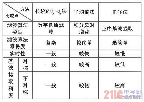
In summary, the performance comparison of the three fundamental wave extraction methods is shown in Table 2.
Table 2 Performance comparison of three fundamental wave extraction methods
5 Conclusion
This paper starts with three fundamental wave extraction methods of active power filters, focusing on the ip-iq theory based on instantaneous reactive power, and then analyzes how to extract the fundamental wave component, which is the key to separating harmonics, and analyzes the advantages and disadvantages of the three methods. Based on the theory of the three fundamental wave extraction methods, MATLAB/Sinmulink is used to simulate and analyze the fundamental wave extraction of active power filters, and compare the three simulation waveforms. The simulation results show that when the grid voltage is distorted or not and whether the load is symmetrical, the three methods can effectively extract the fundamental wave in real time. The best real-time method is the average method, followed by the traditional ip-iq method, and the positive sequence fundamental wave extraction method is the worst. This paper makes some comparisons of the three fundamental wave extraction methods from the perspective of simulation and theoretical algorithms, which can be used as the theoretical and experimental basis for the fundamental wave extraction and harmonic compensation of active power filters.
Previous article:Design and implementation of maximum power point tracking inverter based on IR2101
Next article:USB-OTG Bus Port ESD Protection Array [Vishay]
- Popular Resources
- Popular amplifiers
- MathWorks and NXP Collaborate to Launch Model-Based Design Toolbox for Battery Management Systems
- STMicroelectronics' advanced galvanically isolated gate driver STGAP3S provides flexible protection for IGBTs and SiC MOSFETs
- New diaphragm-free solid-state lithium battery technology is launched: the distance between the positive and negative electrodes is less than 0.000001 meters
- [“Source” Observe the Autumn Series] Application and testing of the next generation of semiconductor gallium oxide device photodetectors
- 采用自主设计封装,绝缘电阻显著提高!ROHM开发出更高电压xEV系统的SiC肖特基势垒二极管
- Will GaN replace SiC? PI's disruptive 1700V InnoMux2 is here to demonstrate
- From Isolation to the Third and a Half Generation: Understanding Naxinwei's Gate Driver IC in One Article
- The appeal of 48 V technology: importance, benefits and key factors in system-level applications
- Important breakthrough in recycling of used lithium-ion batteries
- Innolux's intelligent steer-by-wire solution makes cars smarter and safer
- 8051 MCU - Parity Check
- How to efficiently balance the sensitivity of tactile sensing interfaces
- What should I do if the servo motor shakes? What causes the servo motor to shake quickly?
- 【Brushless Motor】Analysis of three-phase BLDC motor and sharing of two popular development boards
- Midea Industrial Technology's subsidiaries Clou Electronics and Hekang New Energy jointly appeared at the Munich Battery Energy Storage Exhibition and Solar Energy Exhibition
- Guoxin Sichen | Application of ferroelectric memory PB85RS2MC in power battery management, with a capacity of 2M
- Analysis of common faults of frequency converter
- In a head-on competition with Qualcomm, what kind of cockpit products has Intel come up with?
- Dalian Rongke's all-vanadium liquid flow battery energy storage equipment industrialization project has entered the sprint stage before production
- Allegro MicroSystems Introduces Advanced Magnetic and Inductive Position Sensing Solutions at Electronica 2024
- Car key in the left hand, liveness detection radar in the right hand, UWB is imperative for cars!
- After a decade of rapid development, domestic CIS has entered the market
- Aegis Dagger Battery + Thor EM-i Super Hybrid, Geely New Energy has thrown out two "king bombs"
- A brief discussion on functional safety - fault, error, and failure
- In the smart car 2.0 cycle, these core industry chains are facing major opportunities!
- The United States and Japan are developing new batteries. CATL faces challenges? How should China's new energy battery industry respond?
- Murata launches high-precision 6-axis inertial sensor for automobiles
- Ford patents pre-charge alarm to help save costs and respond to emergencies
- New real-time microcontroller system from Texas Instruments enables smarter processing in automotive and industrial applications
- Share: Debugging of SIM7020 and NB-IOT
- mini risc mcu source code
- The design application of TGA2509 is not particularly ideal
- Analysis of the problem that the program cannot run after F28004x online debugging reset
- Share a PD fast charging power deception chip CH224 is very practical
- Alloy sampling resistor series
- TI's Class AB car amplifier chip recommendations
- I am majoring in measurement and control, and am planning to work in the embedded system industry. Could you please tell me if this is the right major for me?
- Motor drive video
- Complementary PWM generation and dead zone control module of c2000

 A review of deep learning applications in traffic safety analysis


 京公网安备 11010802033920号