The R-78xx series is divided into multiple small series according to different usage characteristics. The working environment temperature of all SMD and SIP series reaches 85°C, and the input voltage range is 4.5-34 V.
1. 3-pin SIP package of R-78xx-0.5 series:
Its pinout and spacing are consistent with the 78xx linear regulator, its component density is extremely high, and it can provide a high-efficiency (97% maximum) maximum output current of 500mA. Its output voltage covers the universal standard 1.5v-15v, and its external dimensions are only 11.5 x 7.6 x 10.2 mm, so it can be used as a direct step-down to replace the traditional 78xx linear regulator, and because of the improved efficiency, R The -78xx-0.5 series eliminates the heat sink required by the 78xx and the PCB board space required to place the heat sink.
2.SMT (Surface Mount Technology) version of R-78xx-0.5:
The input and output voltages are the same as the SIP (single in-line package) version, but an additional ON/OFF pin is added so that the regulator can work in standby mode. The standby current is generally 20μA (maximum value is 35μA). This gives it many advantages in applications with very strict power consumption requirements, such as battery operation. In addition, its output voltage is adjustable, simplifying the design of many high-specification power supplies. The SMD (Surface Mount Device) package is a 10-pin dual-row package with a height of 9mm.
The R-78xx-1.0 series members are also divided into the two packaging forms we mentioned above, namely SIP and SMD. It provides an output current of 1000mA. And its physical size and operating environment temperature range are consistent with the SIP and SMD series of R-78xx-0.5, but the maximum input voltage drop is 18V and the maximum output voltage limit is 5V.
When energy comes from various types of batteries at hand, car batteries provided by UltraCaps (the latest high-efficiency capacitor technology used in brake energy storage) or energy conversion systems, the input voltage can be highly variable. Because the R-78xx series can provide an extremely wide input voltage range, many revolutionary new applications have emerged. Here are some examples:
(In the following application, the decoupling capacitor is omitted to make the circuit simpler)
 |
|
Figure 1: Voltage regulator with low ripple and low noise |
The application shown in Figure 1 is a circuit that outputs very low ripple and high efficiency. Two types of voltage regulators with good characteristics are suitable for use. First, the output adjustable voltage regulator R-78A5.0-0.5SMD efficiently reduces the input voltage Ue so that it is only higher than the minimum voltage required to stabilize the voltage Ua required by the LDO linear regulator output. Secondly, the typical input-output voltage difference required for the LDO to output 0.5 A current is 150-300 mV. R1 and R2 are used to set the required output voltage value. The low noise output of R-78A5.0-0.5SMD enables the LDO to quickly stabilize the voltage and control the ripple to 20mVp-p. This circuit is ideal for sensitive sensors or analog-to-digital/digital-to-analog applications. Even accounting for the current leakage through the LDO to ground, this circuit still has an overall efficiency of 86%.
 |
|
Figure 2: Reverse IBA (internal bus structure) |
A familiar circuit similar to Figure 2 used for high-power power supplies is the "internal bus architecture", or IBA for short. The IBA topology uses an isolation converter to step down the main supply voltage to the internal bus voltage, and then uses multiple non-isolated point-of-load (ni POL) converters to perform dc/dc conversion again until the final required circuit voltage. This principle significantly improves efficiency and reduces overall costs.
In this application, in addition to cost reduction, different technical requirements are also the focus. The circuit shown in Figure 2 is suitable for low power power supplies and provides an optimal solution. In this line, the non-isolated DC/DC converter R-785.0-yy converts a highly variable input voltage into an accurate and stable 5V bus voltage, so the subsequent isolated DC/DC converter can obtain a highly stable input voltage. , so that a tight tolerance voltage can be output even without further modulation. The overall efficiency of this series-connected DC/DC converter can still reach 75%, which is higher than the much more expensive all-in-one solution and saves printing board space. The choice of countercurrent current separation is mainly due to cost considerations. The original IBA layout saves costs and improves overall efficiency because the system only uses one isolator, while the cost advantage of the reverse IBA lies in the use of low-power isolated DC/DC converters that are practical, widely used and low-priced.
A further advantage of the modular solution is that any output voltage can be combined in any combination to suit the designer's supply requirements. The wide input voltage feature is useful in systems with multiple supply sources and requiring battery backup to eliminate power outages. Considering the requirements of a battery-powered system or similar energy storage system, refer again to Figure 2. When the stored energy is released, the output voltage tends to drop; while during charging the output voltage rises. The above-mentioned converter can maintain normal output during the entire charging and discharging process. The lower the internal bus voltage, the more energy a single release is required before the output becomes abnormal. It is worth emphasizing that if a very low bus voltage is selected, the efficiency of the subsequent converter will also be relatively reduced.
 |
|
Fig 3: Energy Storage Circuit |
 |
|
Fig 4: Voltage vs Time Graph |
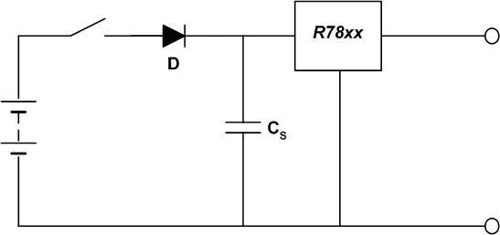
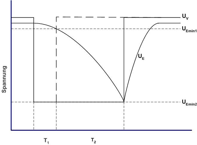
In applications where temporary power supply interruptions need to be considered, auxiliary energy reserves, i.e. backup capacitors, are often used. A similar idea to the previous battery-powered application is used here. The smaller the backup capacitor capacity, the greater the voltage drop when a single release of energy, which reduces the board space requirements a lot, especially when a higher supply voltage is used. The circuit in Figure 3 prevents mains supply interruptions from affecting the output. When the input voltage drops below the capacitor voltage value, diode D prevents the reverse discharge of the backup capacitor Cs. Figure 4 shows the voltage versus time when the power supply is interrupted. UE is the voltage value of the reserve capacitor, UV is the supply voltage value, UEmin1 is the minimum allowed output voltage, and UEmin2 is the minimum allowed internal bus voltage. If the output voltage is obtained by passing the internal bus voltage through the boost converter, then the backup capacitor can be discharged more completely. This allows smaller backup capacitors to handle larger power interruptions.
in conclusion:
RECOM's R78 series converters not only have the advantages of high component density (8.5 W/cm3), small size (0.9cm3) and favorable price, but also have the high-tech advantages listed above. However, when comparing their different solutions, the total cost and total space requirements of the entire system often need to be compared.
Recom is a professional power supply manufacturer with a history of more than 30 years. It has established a solid technical reputation in the power supply industry. Its products range from the world's smallest "IC type" surface mount to the most efficient step-down DC-DC. module. RECOM has the ability to provide technical support worldwide, not only responding to customer inquiries, but also providing customers with a full range of technical solutions from product design to product delivery, including some large-volume products. Special price plans. RECOM's DC-DC module has the characteristics of smallest size and smallest power consumption.
Previous article:Discussion on a kind of UPS leakage protection
Next article:charge pump
- MathWorks and NXP Collaborate to Launch Model-Based Design Toolbox for Battery Management Systems
- STMicroelectronics' advanced galvanically isolated gate driver STGAP3S provides flexible protection for IGBTs and SiC MOSFETs
- New diaphragm-free solid-state lithium battery technology is launched: the distance between the positive and negative electrodes is less than 0.000001 meters
- [“Source” Observe the Autumn Series] Application and testing of the next generation of semiconductor gallium oxide device photodetectors
- 采用自主设计封装,绝缘电阻显著提高!ROHM开发出更高电压xEV系统的SiC肖特基势垒二极管
- Will GaN replace SiC? PI's disruptive 1700V InnoMux2 is here to demonstrate
- From Isolation to the Third and a Half Generation: Understanding Naxinwei's Gate Driver IC in One Article
- The appeal of 48 V technology: importance, benefits and key factors in system-level applications
- Important breakthrough in recycling of used lithium-ion batteries
- Innolux's intelligent steer-by-wire solution makes cars smarter and safer
- 8051 MCU - Parity Check
- How to efficiently balance the sensitivity of tactile sensing interfaces
- What should I do if the servo motor shakes? What causes the servo motor to shake quickly?
- 【Brushless Motor】Analysis of three-phase BLDC motor and sharing of two popular development boards
- Midea Industrial Technology's subsidiaries Clou Electronics and Hekang New Energy jointly appeared at the Munich Battery Energy Storage Exhibition and Solar Energy Exhibition
- Guoxin Sichen | Application of ferroelectric memory PB85RS2MC in power battery management, with a capacity of 2M
- Analysis of common faults of frequency converter
- In a head-on competition with Qualcomm, what kind of cockpit products has Intel come up with?
- Dalian Rongke's all-vanadium liquid flow battery energy storage equipment industrialization project has entered the sprint stage before production
- Allegro MicroSystems Introduces Advanced Magnetic and Inductive Position Sensing Solutions at Electronica 2024
- Car key in the left hand, liveness detection radar in the right hand, UWB is imperative for cars!
- After a decade of rapid development, domestic CIS has entered the market
- Aegis Dagger Battery + Thor EM-i Super Hybrid, Geely New Energy has thrown out two "king bombs"
- A brief discussion on functional safety - fault, error, and failure
- In the smart car 2.0 cycle, these core industry chains are facing major opportunities!
- Rambus Launches Industry's First HBM 4 Controller IP: What Are the Technical Details Behind It?
- The United States and Japan are developing new batteries. CATL faces challenges? How should China's new energy battery industry respond?
- Murata launches high-precision 6-axis inertial sensor for automobiles
- Ford patents pre-charge alarm to help save costs and respond to emergencies
- FOC sensorless motor control video
- Implementation of a sensorless, low-cost, high-speed, low- and medium-power BLDC controller
- Design of embedded network interface controller based on FPGA
- SHT31 Review Summary
- The differential voltage measured by the oscilloscope when the RS485 bus is idle is ±3.7V, and the periodic waveform with a frequency of 50hz
- What are the functions of magnetic beads and capacitors? How to choose the impedance of magnetic beads and the size of capacitors?
- Why would the filter added to the final stage cavity be burned?
- 【Beetle ESP32-C3】GNSS test
- Arteli AT32 uses GPIO to simulate HDMI CEC case
- Analyze the cause of tms320c6455 burning

 Integrated Circuit Testing Technology (Wu Qianwen)
 CVPR 2023 Paper Summary: Vision Applications and Systems


 京公网安备 11010802033920号