The option for circuit designers to turn power lines on and off in electronic systems may sound like a small thing, but there are many aspects to consider for successful implementation.
In some electronic systems, it is necessary to disconnect the power lines. For example, it might be cutting off battery voltage to preserve battery charge, or disconnecting a load from a live line. Ideally, a mechanical switch would be used for this purpose. However, if switching via an electronic signal is required, then it is usually more appropriate to use an electronic switch. This type of electronic switch may use MOSFETs as switching elements. In addition to purely discrete solutions with MOSFETs, electronic switching can be easily implemented using a variety of semiconductor ICs.

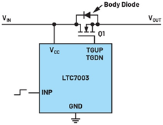
Figure 1. Switching power lines using N-channel MOSFETs and a stand-alone driver circuit, the LTC7003
First, it must be decided whether the switching element is an N-channel or P-channel MOSFET. Both may be appropriate. However, compared with P-channel MOSFET, N-channel MOSFET has lower resistance, so the loss in the on-state is also lower. The disadvantage lies in the driving aspect of N-channel MOSFET. where the voltage required by the gate is higher than the available power line voltage. Therefore, some form of charge pump must be included in the driver IC. P-channel MOSFETs do not require this type of boosting. However, there is a wide selection of N-channel MOSFETs.
Next, you need to choose whether to integrate the power switch and driver in a single package or use a two-chip solution that puts the driver circuit in a separate IC and the corresponding MOSFET in another package. A selection of switches that have been optimized for the driver circuit further supports integration in the same package. In this case, the switch is generally well protected and does not experience overloading during use. This fully integrated solution also has disadvantages, including fewer related products on the market and higher costs.
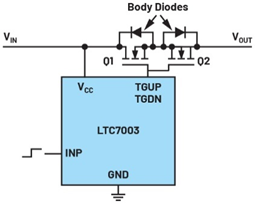
In the third step, it must be determined whether a single MOSFET is sufficient to constitute a mechanical switch . MOSFETs have a body diode and, therefore, can only switch current in one direction. If the application requires a complete disconnection of the line, ensuring that current cannot flow in either direction, then a solution is required in which two MOSFETs are connected in anti-series with each other. Figure 2 shows this switch-level configuration.

Figure 2. Circuit in which two N-channel MOSFETs are connected back-to-back to block current in both directions of the circuit.
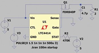
Finally, the appropriate integrated circuit must be selected, either the driver for the MOSFET or the package containing the MOSFET and driver. This step sounds simple, but is actually quite tedious. A load switch is usually required. However, the range of options is not large. In many cases, hot-swappable controllers, electronic fuses, surge protectors, ideal diodes, and power path controllers can be used, depending on the application and the additional monitoring capabilities required. Most of these devices contain switch pins that can cut off the current flow when needed. With Analog Devices' LTspice® simulation tools, you can confirm that the solution's precise behavior meets specifications.

Figure 3. LTspice simulation using the LTC4414 low-loss PowerPath™ controller as load switch
Depending on the specific application, disconnecting the supply voltage can be very complex. However, a special MOS driver IC with switch control pins can be used to reduce design difficulty.
About Analog Devices
Analog Devices, Inc. (NASDAQ: ADI) plays a vital role at the center of the modern digital economy, transforming real-world phenomena into actionable products with its broad portfolio of analog and mixed-signal, power management, RF, digital and sensing technologies. Insight into meaning. ADI serves 125,000 customers worldwide and provides more than 75,000 products in the industrial, communications, automotive and consumer markets. Analog Devices is headquartered in Wilmington, Massachusetts.
About the author
Frederik Dostal studied microelectronics at the University of Erlangen in Germany. He started in the power management business in 2001 and held various applications engineer positions, including 4 years in Phoenix, Arizona working on switch mode power supplies. He joined Analog Devices in 2009 and worked as a power management field applications engineer at ADI in Munich.
Previous article:Silicon Carbide (SiC) Power Management Solution
Next article:WPG Group launches 500W server power solution based on Onsemi products
- Popular Resources
- Popular amplifiers
- MathWorks and NXP Collaborate to Launch Model-Based Design Toolbox for Battery Management Systems
- STMicroelectronics' advanced galvanically isolated gate driver STGAP3S provides flexible protection for IGBTs and SiC MOSFETs
- New diaphragm-free solid-state lithium battery technology is launched: the distance between the positive and negative electrodes is less than 0.000001 meters
- [“Source” Observe the Autumn Series] Application and testing of the next generation of semiconductor gallium oxide device photodetectors
- 采用自主设计封装,绝缘电阻显著提高!ROHM开发出更高电压xEV系统的SiC肖特基势垒二极管
- Will GaN replace SiC? PI's disruptive 1700V InnoMux2 is here to demonstrate
- From Isolation to the Third and a Half Generation: Understanding Naxinwei's Gate Driver IC in One Article
- The appeal of 48 V technology: importance, benefits and key factors in system-level applications
- Important breakthrough in recycling of used lithium-ion batteries
- LED chemical incompatibility test to see which chemicals LEDs can be used with
- Application of ARM9 hardware coprocessor on WinCE embedded motherboard
- What are the key points for selecting rotor flowmeter?
- LM317 high power charger circuit
- A brief analysis of Embest's application and development of embedded medical devices
- Single-phase RC protection circuit
- stm32 PVD programmable voltage monitor
- Introduction and measurement of edge trigger and level trigger of 51 single chip microcomputer
- Improved design of Linux system software shell protection technology
- What to do if the ABB robot protection device stops
- ASML predicts that its revenue in 2030 will exceed 457 billion yuan! Gross profit margin 56-60%
- Detailed explanation of intelligent car body perception system
- How to solve the problem that the servo drive is not enabled
- Why does the servo drive not power on?
- What point should I connect to when the servo is turned on?
- How to turn on the internal enable of Panasonic servo drive?
- What is the rigidity setting of Panasonic servo drive?
- How to change the inertia ratio of Panasonic servo drive
- What is the inertia ratio of the servo motor?
- Is it better for the motor to have a large or small moment of inertia?
- Small Cell Networks and the Evolution of 5G
- A very down-to-earth question: How do capacitors absorb ESD?
- C Language Core Technology (Original Book 2nd Edition)
- Do you know the chip manufacturer of this Bluetooth module?
- Disassembly of isolator
- Which domestic motor drive company do you think is the most promising?
- What should we pay attention to when developing headphone speakers?
- Analysis of Optimized Programming of TMS320C6000 Embedded System
- 【Qinheng RISC-V core CH582】 3 Light routines and button acquisition initial test
- Record - Implementing USB virtual serial port on STM32 based on RTT

 BA3404FV-E2


 京公网安备 11010802033920号