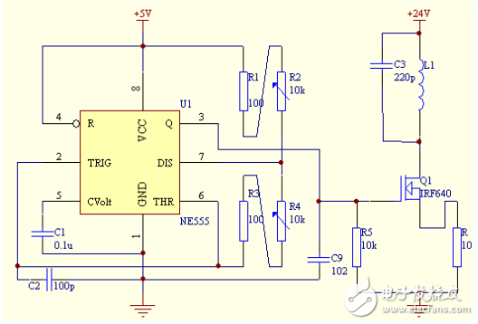
Main oscillator circuit:
NE555 is used as the waveform generation circuit. By adjusting the size of the variable resistor of 555, the frequency and duty cycle of the output square wave can be changed within a certain range. When the LC oscillation circuit changes, adjusting the size of the variable resistor can generate a waveform of the corresponding frequency, forming resonance with the LC circuit.
Power amplifier circuit:
The field effect tube is used as the power amplifier element, the power consumption is lower than that of the triode, the driving power is small, and it is easy to use. It can be driven directly by using the output of NE555.
Unit circuit:
1 The power circuit uses 24V and 5V power supplies to power the field effect tube NE555 respectively. After the transformer is used to transform the power, the 7812 and 7912 voltage regulator modules are used to generate 24V points, and then the 7805 power supply is used to generate 5V power. And it is important to note that the two power supplies share the same ground.

2 The signal generating circuit uses NE555 to form a signal generator with an oscillation frequency of about 500KHZ, which provides an excitation signal for the power amplifier circuit. By adjusting the size of the variable resistor of 555, the frequency and duty cycle of the output square wave can be changed within a certain range, and the required frequency can be adjusted.

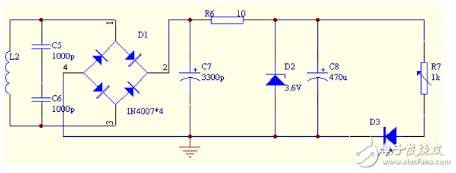
3 Design of the receiving end charging control circuit After the electric energy is received by the coil, the high-frequency AC voltage is full-wave rectified by the IN4007 rectifier tube, filtered by a 2200uf capacitor, and then stabilized by a 3.3V Zener diode. The output DC power provides a more stable working voltage for the light bulb (battery).

Improvement ideas:
(1) When the transmission distance and coil parameters are fixed, the transmitting end needs to have a higher frequency and the transmitting coil should work in a resonant state to increase the transmission efficiency.
(2) One way to increase the distance is to increase the voltage of the transmitter circuit.
(3) This design uses IN4007 rectifier tube for rectification, and the average voltage drop of the tube is 0.8V. The conduction loss is large and it is not suitable for use in the receiving circuit. If Schottky diode is used, the tube loss can be greatly reduced, and the power utilization rate is higher.
(4) The copper wire diameter, coil diameter, number of turns and winding method not only determine the inductance value of the coil, but also affect its transmission efficiency.
Previous article:LM317 power supply application circuit design combination analysis
Next article:Analysis of the causes of EMI generated by switching power supplies and anti-interference countermeasures
- Popular Resources
- Popular amplifiers
-
 Signal Integrity and Power Integrity Analysis (Eric Bogatin)
 -
 Three-Phase 11 kW PFC + LLC Electric Vehicle On-Board Charging (OBC) Platform User Manual (ONSEMI Semiconductor)
 -
 Cadence Allegro Practical Strategy and High-Speed PCB Design
 -
 Introduction to the classification, application, composition and model of phase-locked loop
- MathWorks and NXP Collaborate to Launch Model-Based Design Toolbox for Battery Management Systems
- STMicroelectronics' advanced galvanically isolated gate driver STGAP3S provides flexible protection for IGBTs and SiC MOSFETs
- New diaphragm-free solid-state lithium battery technology is launched: the distance between the positive and negative electrodes is less than 0.000001 meters
- [“Source” Observe the Autumn Series] Application and testing of the next generation of semiconductor gallium oxide device photodetectors
- 采用自主设计封装,绝缘电阻显著提高!ROHM开发出更高电压xEV系统的SiC肖特基势垒二极管
- Will GaN replace SiC? PI's disruptive 1700V InnoMux2 is here to demonstrate
- From Isolation to the Third and a Half Generation: Understanding Naxinwei's Gate Driver IC in One Article
- The appeal of 48 V technology: importance, benefits and key factors in system-level applications
- Important breakthrough in recycling of used lithium-ion batteries
- Innolux's intelligent steer-by-wire solution makes cars smarter and safer
- 8051 MCU - Parity Check
- How to efficiently balance the sensitivity of tactile sensing interfaces
- What should I do if the servo motor shakes? What causes the servo motor to shake quickly?
- 【Brushless Motor】Analysis of three-phase BLDC motor and sharing of two popular development boards
- Midea Industrial Technology's subsidiaries Clou Electronics and Hekang New Energy jointly appeared at the Munich Battery Energy Storage Exhibition and Solar Energy Exhibition
- Guoxin Sichen | Application of ferroelectric memory PB85RS2MC in power battery management, with a capacity of 2M
- Analysis of common faults of frequency converter
- In a head-on competition with Qualcomm, what kind of cockpit products has Intel come up with?
- Dalian Rongke's all-vanadium liquid flow battery energy storage equipment industrialization project has entered the sprint stage before production
- Allegro MicroSystems Introduces Advanced Magnetic and Inductive Position Sensing Solutions at Electronica 2024
- Car key in the left hand, liveness detection radar in the right hand, UWB is imperative for cars!
- After a decade of rapid development, domestic CIS has entered the market
- Aegis Dagger Battery + Thor EM-i Super Hybrid, Geely New Energy has thrown out two "king bombs"
- A brief discussion on functional safety - fault, error, and failure
- In the smart car 2.0 cycle, these core industry chains are facing major opportunities!
- The United States and Japan are developing new batteries. CATL faces challenges? How should China's new energy battery industry respond?
- Murata launches high-precision 6-axis inertial sensor for automobiles
- Ford patents pre-charge alarm to help save costs and respond to emergencies
- New real-time microcontroller system from Texas Instruments enables smarter processing in automotive and industrial applications
- RF PA circuit design based on gallium nitride (GaN) devices
- [Project source code] NIOS II custom IP core writing basic framework
- What circuit is generally used to achieve the LED light gradually turning on and off function?
- Sugar Glider Part 7: Software Design of the Exercise Reward System for Sugar Glider Based on RSL10
- The magical problem encountered by KICAD
- X-NUCLEO-IKS01A3 Official Technical Data
- AT32F425-Evaluation Report-Serial Port and Waveform Display Host Computer Debugging-09
- There is a car image simulation project for paid consultation, using the Freescale solution
- Take a look at the USB Host microcontroller in gaming peripherals
- What is the component B93 on the circuit board?

 Signal Integrity and Power Integrity Analysis (Eric Bogatin)
 Three-Phase 11 kW PFC + LLC Electric Vehicle On-Board Charging (OBC) Platform User Manual (ONSEMI Semiconductor)


 京公网安备 11010802033920号