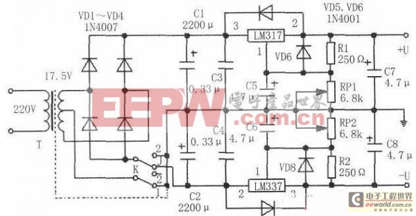
The working principle of the circuit is shown in the figure below. The biggest advantage of this circuit is that it uses two three-terminal adjustable voltage regulators LM317 and LM337. During maintenance use, when the switch K is turned to position "1", the AC voltage of 17.5V×2 is reduced from the secondary of the power transformer T, and is sent to the input terminals of LM317 and LM337 respectively after rectification by VD1~VD4, and then controlled by sampling resistors R1, R2 and output voltage adjustment potentiometers RPl, RP2, a continuously adjustable voltage of ±1.25~15V can be obtained at the output terminal. When the switch K position is turned to "2", the power transformer T group with double output groups is used as a single group, and is only sent to LM317 after rectification and filtering to obtain a voltage of +1.25~30V. Single power supply output, so it can be easily used in maintenance circuits that require a single power supply or a slightly higher voltage.

R1 and R2 in the circuit are used to protect the load current of not less than 5mA; C5 and C6 are bypass capacitors designed to reduce the ripple voltage across R1 and R2 of the sampling circuit; C7 and c8 are designed to prevent the self-excitation phenomenon that occurs when the output load is capacitive; VD5 and VD7 are used to prevent the discharge current of c7 and c8 from damaging the three-terminal voltage regulator when a short circuit occurs at the output/input terminal; VD6 and VD8 are used to prevent the discharge current of C5 and C6 from damaging the three-terminal voltage regulator when a short circuit occurs at the output terminal.

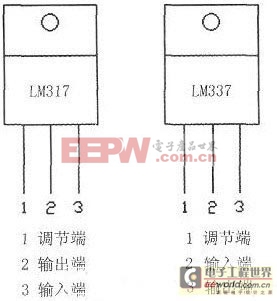
The pin functions of LM317 and LM337 are shown in Figure 2. All capacitors in this circuit are selected to have a withstand voltage greater than 50V. The power consumption of the two three-terminal adjustable voltage regulator blocks is about 15W.
Remember to add enough heat sinks and the dotted line of the transformer center tap must be firmly grounded to prevent interference from AC noise.
Previous article:Analysis of EMI Causes and Anti-interference Measures Based on Switching Power Supply
Next article:Analysis and improvement of common faults in three-phase power supply
- Popular Resources
- Popular amplifiers
- MathWorks and NXP Collaborate to Launch Model-Based Design Toolbox for Battery Management Systems
- STMicroelectronics' advanced galvanically isolated gate driver STGAP3S provides flexible protection for IGBTs and SiC MOSFETs
- New diaphragm-free solid-state lithium battery technology is launched: the distance between the positive and negative electrodes is less than 0.000001 meters
- [“Source” Observe the Autumn Series] Application and testing of the next generation of semiconductor gallium oxide device photodetectors
- 采用自主设计封装,绝缘电阻显著提高!ROHM开发出更高电压xEV系统的SiC肖特基势垒二极管
- Will GaN replace SiC? PI's disruptive 1700V InnoMux2 is here to demonstrate
- From Isolation to the Third and a Half Generation: Understanding Naxinwei's Gate Driver IC in One Article
- The appeal of 48 V technology: importance, benefits and key factors in system-level applications
- Important breakthrough in recycling of used lithium-ion batteries
- LED chemical incompatibility test to see which chemicals LEDs can be used with
- Application of ARM9 hardware coprocessor on WinCE embedded motherboard
- What are the key points for selecting rotor flowmeter?
- LM317 high power charger circuit
- A brief analysis of Embest's application and development of embedded medical devices
- Single-phase RC protection circuit
- stm32 PVD programmable voltage monitor
- Introduction and measurement of edge trigger and level trigger of 51 single chip microcomputer
- Improved design of Linux system software shell protection technology
- What to do if the ABB robot protection device stops
- Wiring harness durability test and contact voltage drop test method
- From probes to power supplies, Tektronix is leading the way in comprehensive innovation in power electronics testing
- From probes to power supplies, Tektronix is leading the way in comprehensive innovation in power electronics testing
- Sn-doped CuO nanostructure-based ethanol gas sensor for real-time drunk driving detection in vehicles
- Design considerations for automotive battery wiring harness
- Do you know all the various motors commonly used in automotive electronics?
- What are the functions of the Internet of Vehicles? What are the uses and benefits of the Internet of Vehicles?
- Power Inverter - A critical safety system for electric vehicles
- Analysis of the information security mechanism of AUTOSAR, the automotive embedded software framework
- Brief Analysis of Automotive Ethernet Test Content and Test Methods
- You can use FIND to check which library a certain component is in in the PROTEL schematic. You can also check which library a certain package is in. Why is it not there?
- Can RS485 communicate stably using parallel wires (non-twisted pair)? 5m wire length, 9600bps
- TI Wired and Wireless Communications in Electric Vehicle Battery Management
- [CH563L Review] Part 1 Based on the official uCos introductory Hello World
- Why is there a "red dot" on my forum icon?
- Is the signal mentioned in Nyquist sampling theorem limited to sine (cosine) signal form?
- Thank you for being there, thank you for being polite!
- How to locate the code and data of C program
- Color screen printing limit for color segment screen
- RF Personal Experience Sharing Series

 EGN045MK


 京公网安备 11010802033920号