The emergence of the emerging field of semiconductor lighting has made engineers who specialize in power electronics, optics, and thermal management (mechanical engineering) in high demand. Currently, there are not many engineers who are experienced in all three fields, which usually means that the background of system engineers or overall product engineers must be related to these three fields, and they must also collaborate with engineers in other fields as much as possible. System engineers often bring their habits or accumulated experience in their original fields into the design work, which is similar to the situation encountered by an electronic engineer who mainly studies digital systems when he switches to solving power management problems: they may rely on pure simulation and directly wire the circuit board without testing the power supply on the bench because they do not realize that switching regulators require careful inspection of the circuit board layout and that it is difficult for the actual working conditions to be consistent with the simulation without bench testing.
In the process of designing LED lamps, when the system architect is an electronic power expert, or the power supply design is contracted to an engineering company, some common habits in standard power supply design will appear in LED driver design. Some habits are very useful because LED drivers are very similar to traditional constant voltage sources in many ways. Both types of circuits operate in a wide input voltage range and large output power. In addition, both types of circuits face the challenges of connecting to AC power, DC regulated power rails or batteries.
Power electronics engineers are used to always want to ensure high accuracy of output voltage or current, but this is not a good habit for LED driver design. Digital loads such as FPGAs and DSPs require lower core voltages, which in turn require stricter control to prevent higher bit error rates. Therefore, the tolerance of digital power rails is usually controlled within ±1% or smaller than their nominal values, which can also be expressed in absolute values, such as 0.99V to 1.01V. When the design habits of traditional power supplies are introduced into the field of LED driver design, the problem usually arises: in order to achieve strict control of output current tolerance, more power will be wasted and more expensive devices will be used, or both.
Cost pressure
The ideal power supply is low cost, 100% efficient, and does not take up space. Power electronics engineers are used to listening to customers, and they will do their best to meet those requirements, trying to design the system within the smallest space and budget. This is no exception when designing LED drivers. In fact, it faces greater budget pressure because traditional lighting technology has been fully commercialized and its price is very low. Therefore, it is very important to spend every penny under the budget, which is also where some power electronics designers and engineers are "led astray" by old habits.
To control the LED current to the same accuracy as the supply voltage to the digital load would waste both power and money. 100mA to 1A is the current range for most current products, especially now that 350mA (or more precisely, the current density of the optoelectronic semiconductor junction is 350mA/mm2) is the usual compromise between thermal management and lighting efficiency. The integrated circuits that control the LED drivers are silicon-based, so there is a typical bandgap in the range of 1.25 V. To achieve a 1% tolerance at 1.25V, a voltage range of ±12.5mV is required. This is not difficult to achieve, and low-cost voltage reference circuits or power control ICs that can achieve this tolerance or better are available in a wide variety of low-cost and low-cost ranges. When controlling the output voltage, high-precision resistors can be used to feedback the output voltage at very low power (as shown in Figure 1a). To control the output current, some adjustments need to be made to the feedback method, as shown in Figure 1b. This is currently the only and simplest way to control the output current.
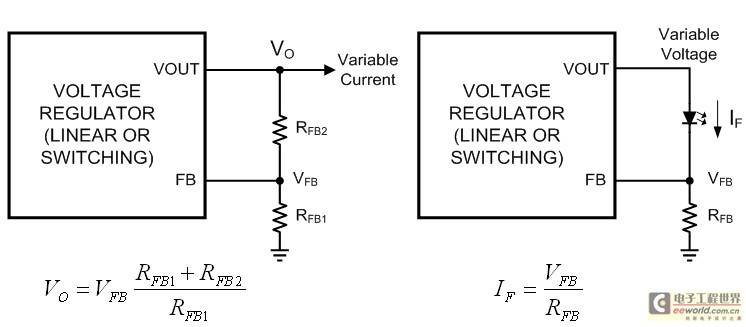
Figure 1a: Voltage feedback; Figure 1b: Current feedback
A closer look reveals a major drawback to this approach: the load and feedback circuits are identical. The reference voltage is added across a resistor in series with the LED, which means that the higher the reference voltage or LED current, the more power the resistor dissipates. As a result, the first generation of dedicated LED driver ICs had much lower reference voltages than today’s offerings, similar to battery chargers. Lower voltage means lower power consumption, which also means smaller, cheaper, and lower-loss current-sense resistors. In the simple, low-side feedback environment of Figure 1b, 200mV is a common voltage choice. However, achieving a ±1% tolerance on a 200mV reference voltage requires a very expensive integrated circuit, which now has a ±2mV tolerance relative to the nominal reference voltage. While it is not impossible to achieve, higher accuracy comes at a higher cost. A ±2mV tolerance requires the production, testing, and binning techniques required for a high-precision voltage reference, and the additional cost should be spent on a smarter LED driver. The value of the new expense is the addition of a feedback loop that uses light output (rather than current output) to control how the LED is driven.
Measuring light output
Just as digital product designers resort to simulation to solve uncertainties in power supply design, system architects who are power electronics engineers think of high-precision output when designing LED lamps. LED manufacturers have made it clear that luminous flux is proportional to forward current. Driving all LEDs with the same current will produce the same luminous flux for each LED. Therefore, power electronics engineers conclude that high-precision current is a must. In doing so, they forget that the lumens and lux values of light output (not amperes) are the key. Measuring current is easy, while measuring light requires expensive and large equipment, such as the integrating sphere shown in Figure 2, which most electronic engineers are not familiar with.
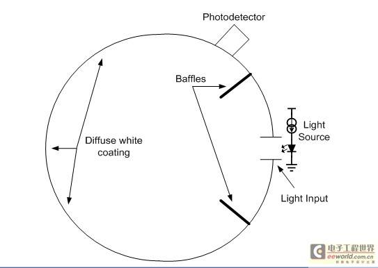
Figure 2: Cross-section of an optical integrating sphere
Furthermore, even though current sources with a ±0.1% tolerance (which would be quite expensive) have great market value, it does little to produce tight tolerance values in actual light output. This can be confirmed by looking at the binning of LED luminous flux. Table 1 shows the luminous flux binning results of high-end cool white LEDs at 350mA and 25°C from the world's three top power optoelectronic semiconductor manufacturers. Note that the last column is the average tolerance of each bin, not the tolerance within the range of all luminous flux bins.
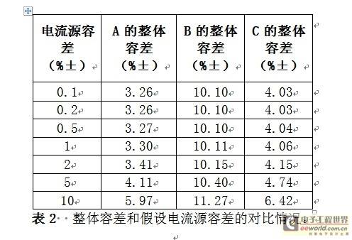
Table 1 Luminous flux binning results of high-end cool white LEDs from the world's top three power optoelectronic semiconductor manufacturers at 350 mA and 25°C. Calculated light output accuracy
Knowing that the LED light output from a single flux bin will have a tolerance of ±3% to ±10%, a system engineer might conclude that the drive current tolerance must be as tight as possible. However, this is not statistically correct. A common but incorrect assumption is that the overall tolerance for any value is simply the sum of the worst-case values. The tolerance of the current source powering the LED and the tolerance of the LED light flux are unrelated - they are independent from the outset. For two unrelated factors X and Y, the overall tolerance Z is not the sum of the tolerances of X and Y, but should be calculated using the following expression:

Table 2 and Figure 3 show the overall tolerance versus the assumed current source tolerance, assuming that the LED light output varies linearly with forward current in the 350mA region.

Table 2. Comparison of overall tolerance and assumed current source tolerance.
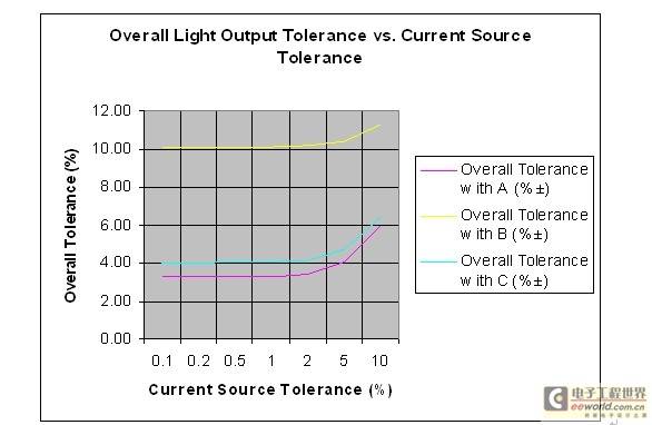
Figure 3: Comparison of overall tolerance and assumed current source tolerance.
Equation (1) shows that the lowest tolerance factor has a greater effect than the others, and the actual overall tolerance value is much better than the sum of the worst-case tolerances of the individual factors, especially when one factor is much better than the others. Figure 3 shows that the most reasonable goal for the current source tolerance is to keep it within the tolerance range of the LED light output. Keep in mind that many luminaires use LEDs from different bins for cost reasons. Table 3 lists the tolerance values for the same LED in the highest two, three, and four luminous flux bins.

Table 3 Tolerance values of the same LED in the highest two-level, three-level and four-level luminous flux bins Dimming control
LED manufacturers and their distribution partners are working hard to improve the luminous flux tolerance of their products, providing finer bins within a reasonable cost range. For designers who want their products to last for 5 years or 50,000 hours and maintain the same overall light output during the service life, even the tightest flux bins and 0.1% tolerance current sources are difficult to achieve. Because heat and performance degradation over time are two important factors that reduce the luminous flux of LEDs, even 0.001% tolerance of current sources and LED luminous flux cannot solve this problem. Considering these losses, designers of high-quality solid-state lighting products must find power supplies with additional feedback loops, that is, heat and light sources. For this, dimming control is required, and integrated circuits that can perform linear and PWM control of output current become the best choice.
For example, National Semiconductor's LM3409 and LM3424 are both LED driver control ICs that are second-generation current sources for semiconductor lighting. Both products can control the average LED current value through a variable resistor or voltage source, and can provide a dedicated input signal for the PMW dimming signal. In addition to the linear control loop, the analog regulation function of the LM3409 and LM3424 also allows system designers to make their own choices between the output current accuracy and the size, cost and power consumption of the current detection resistor. The LM3409/09HV control buck circuit shown in Figure 4 is the most commonly used circuit mode in power LED drivers. The LM3424 in Figure 5 can be used as a boost regulator LED driver, as well as a buck/boost, SEPIC, flyback or even a "floating" buck circuit.
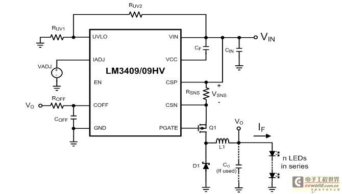
Figure 4: LM3409/09HV buck LED driver
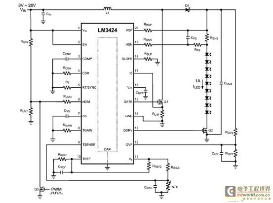
Figure 5: LM3424 boost LED driver
Applications requiring light control
Streetlights are a good example of a light source because they have strict legal standards. For road lights, EU countries specify their minimum and maximum light output and lighting modes. For LED streetlights to meet this regulation and provide a service life of five years or more, the design must take into account the immediate loss of luminous flux caused by heat, as well as the loss of flux caused by performance degradation over a longer period of time.
A natural approach is to use a light sensor such as a photodiode in a linear control loop. On the first day of the system, only a portion of the total available drive current should be used, considering that over time the drive current will slowly increase to an upper limit to maintain constant light output. The photodiode can be biased and converted to a pulse width modulated signal, which will help maintain a more constant relative color temperature over the dimming range. The linear control loop is simpler and the dimming range is generally smaller. PWM control is more useful when the light output is controlled based on different time of day, motion sensors or other power saving measures. Figure 6 shows a hypothetical block diagram of an LED lamp with a longer life and constant light output.
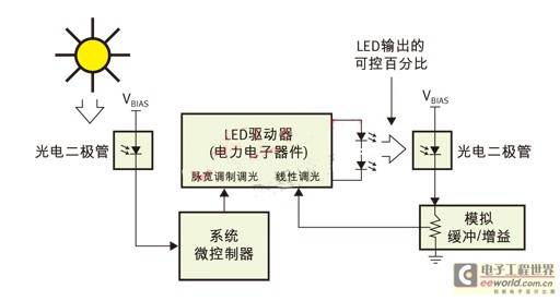
Figure 6: PWM (pulse width modulation) is used for day/night control and linear control is used for light output.
Conclusion
Output current accuracy is only one aspect of evaluating LED driver performance, but when the luminous flux tolerance of the LED itself is kept at a level far better than ±1%, even if the current source tolerance is as strict as the tolerance of the voltage rail in the digital processor, it is almost meaningless. The average LED current tolerance should be almost equal to the luminous flux tolerance. This article explores an ideal situation based on the error of a single bin and gives some practical examples. These examples use two or more bins of LEDs, and their tolerances can also be more easily achieved. ±5%, ±10% or higher. In additional control loops, the cost should be spent on 1% current control, and the power can be used for higher detection voltages. Some LED lamps will emphasize simplicity, practicality and low cost. At this time, even linear dimming will be too complicated and expensive, but if you want to design a lamp that fully utilizes the performance of LEDs, you need to use linear control or PWM methods or a combination of the two to optimize product performance and life.
Previous article:Output Power Measurement in Electrolytic Capacitor-Free LED Driver
Next article:Simple PWM modulator circuit capable of driving LEDs with DC signals
- MathWorks and NXP Collaborate to Launch Model-Based Design Toolbox for Battery Management Systems
- STMicroelectronics' advanced galvanically isolated gate driver STGAP3S provides flexible protection for IGBTs and SiC MOSFETs
- New diaphragm-free solid-state lithium battery technology is launched: the distance between the positive and negative electrodes is less than 0.000001 meters
- [“Source” Observe the Autumn Series] Application and testing of the next generation of semiconductor gallium oxide device photodetectors
- 采用自主设计封装,绝缘电阻显著提高!ROHM开发出更高电压xEV系统的SiC肖特基势垒二极管
- Will GaN replace SiC? PI's disruptive 1700V InnoMux2 is here to demonstrate
- From Isolation to the Third and a Half Generation: Understanding Naxinwei's Gate Driver IC in One Article
- The appeal of 48 V technology: importance, benefits and key factors in system-level applications
- Important breakthrough in recycling of used lithium-ion batteries
- LED chemical incompatibility test to see which chemicals LEDs can be used with
- Application of ARM9 hardware coprocessor on WinCE embedded motherboard
- What are the key points for selecting rotor flowmeter?
- LM317 high power charger circuit
- A brief analysis of Embest's application and development of embedded medical devices
- Single-phase RC protection circuit
- stm32 PVD programmable voltage monitor
- Introduction and measurement of edge trigger and level trigger of 51 single chip microcomputer
- Improved design of Linux system software shell protection technology
- What to do if the ABB robot protection device stops
- Huawei's Strategic Department Director Gai Gang: The cumulative installed base of open source Euler operating system exceeds 10 million sets
- Download from the Internet--ARM Getting Started Notes
- Learn ARM development(22)
- Learn ARM development(21)
- Learn ARM development(20)
- Learn ARM development(19)
- Learn ARM development(14)
- Learn ARM development(15)
- Analysis of the application of several common contact parts in high-voltage connectors of new energy vehicles
- Wiring harness durability test and contact voltage drop test method
- ZigBee transmission based on self-powered switch
- TMS320DM642 Bootmode
- Single chip microcomputer drives 9013 transistor to realize infrared emission circuit diagram
- 【Goodbye 2021, Hello 2022】+Life is getting better and better
- What are the characteristics of such a zero-pole system?
- msp430 program for sed1335
- SDR-Hackrf one
- Truck scale weighing system based on RFID technology application
- Creating an Android emulator with the IMX6 development board
- I want to make some switches related to artificial intelligence, such as developing a traffic violation recognition system. What knowledge do I need to learn?

 CVPR 2023 Paper Summary: Efficient and Scalable Vision
 CA3193AT


 京公网安备 11010802033920号