With the development of LED technology, power LEDs have developed rapidly in the fields of backlight, automobile, outdoor lighting, commercial lighting, etc. However, the output luminous flux of a single LED is currently low. For outdoor lighting, LEDs need to be integrated to achieve the required brightness. In the photoelectric conversion of LEDs, only 10% to 20% of the electrical energy is converted into light output, and the rest is converted into heat energy. The heat is conducted through the LED substrate to the externally installed heat sink for heat dissipation. In order to ensure the life and reliability of LED street lamps, the junction temperature of the LED chip must be controlled below 120°C. LEDs are used for road lighting or tunnel lighting, and must meet the requirements of dustproof, waterproof, lightning strike, wind pressure, etc., so the natural convection cooling method is the best for high-power LED street lamp radiators.
In response to the heat dissipation problem of high-power LED street lamps, domestic and foreign scholars or manufacturers have done a lot of work on the structure and materials of radiators. Liu Jing et al. used the thermal resistance method of equivalent circuit to calculate the thermal resistance of high-power LED lighting and estimated the area of the radiator. Then they used Icepak software to perform modeling analysis, changed the geometric parameters of the radiator structure, and found through analysis and comparison that the change in fin height has the most obvious effect on the heat dissipation performance. Zhang Qi et al. used ANSYS finite element software to conduct thermal analysis on its heat dissipation structure and analyzed the influence of different structural parameters of aluminum heat sink on its temperature field. Through simulation optimization, the mass of the radiator was effectively reduced and the structure of the radiator was optimized. Hu Hongli et al. controlled the heat dissipation of LED lamps based on semiconductor thermoelectric elements and heat pipe technology, and added a waste heat recovery system, which has a complex structure and many accessories, affecting its working stability. Zhang Xuefen designed a variety of high-power LED radiator models, but in the simulation analysis of natural convection for each radiator, a fixed average heat transfer coefficient was used for its surface. Although the calculation area is only the radiator itself, which greatly simplifies the calculation amount, reduces the calculation time, and facilitates the radiator design, due to the complexity of the geometric structure, the average heat transfer coefficient must be accurately obtained through repeated corrections of experiments and numerical calculations. L.Dialameh et al. conducted a three-dimensional numerical simulation optimization of the fin radiator and analyzed the distribution of air velocity at different fin heights and fin spacings; under different fin heights and fin spacings, different average heat transfer coefficients of the fins were obtained.
The appearance of a conventional 50W LED street lamp heat sink is shown in Figure 1. It is large in size, wastes a lot of metal materials, and has high costs, which hinders the industrial application of high-power LED street lamps. This paper uses Fluent software to perform a three-dimensional modeling analysis on this heat sink, studies the coupled heat transfer problem of the heat sink's natural convection heat transfer in a large space, studies the temperature field of the heat sink during the heat dissipation process and the vector field of the surrounding air flow, and improves the structure of the heat sink.
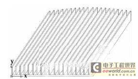
Figure 1 Schematic diagram of the appearance of LED street lamp radiator
1 Radiator Analysis
1.1 Numerical analysis
2.1.1.1 Computational domain
The establishment of the three-dimensional physical model, meshing and boundary conditions are all carried out in the Fluent pre-processing software Gambit. The model calculation domain is shown in Figure 2. The substrate is 4 mm thick, the bottom surface of the substrate is 270 mm × 255 mm, the fin thickness is 2 mm, the maximum spacing in the middle is 16 mm, and the rest are 12 mm. The fin heights from the outside to the middle are 32, 33, 33, 34, 34, 35, 35, 36, 36 and 37 mm.
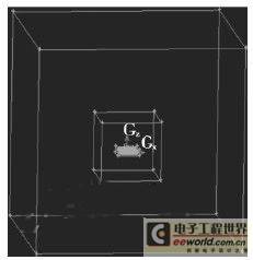
Figure 2 Schematic diagram of the numerical calculation model of the radiator
In order to meet the accuracy of the natural convection coupling calculation of the radiator, the air flow domain must be large enough, and the pressure inlet boundary condition can be applied to the large space. However, if the calculation domain is too large and a sufficiently dense grid is required around the radiator, it will cause too many divided grids, insufficient computer resources (memory, CPU), and too slow calculation. Therefore, we need to use a multi-layer grid drawing method for the calculation domain. In this way, the air flow area near the radiator and the radiator can be divided with a smaller grid unit interval, and the air flow area far from the radiator can use a sparse grid. This can reduce the amount of calculation and shorten the calculation time.
1.1.2 Calculation method
The bottom surface of the heat sink substrate continuously provides heat. The junction between the substrate and the heat sink fins is a coupled problem of heat conduction and convection heat transfer. The fins and the surrounding air undergo natural convection heat transfer. Therefore, the problem is approximately regarded as a coupled problem of heat conduction and convection heat transfer with three-dimensional, steady-state, constant physical properties, and internal heat source. The radiation heat transfer caused by the temperature difference is negligible in the calculation process. Due to the buoyancy force caused by the temperature difference, the Boussinesq hypothesis is introduced in the calculation: 1) The viscous dissipation term in the fluid is negligible; 2) All physical properties except density are constants; 3) Density only considers the terms related to volume force in the momentum equation, and the density in the other terms is treated as a constant. During the numerical calculation, the heat sink and the large space adopt the whole field discretization and whole field solution method, and the heat transfer process in the solid and fluid is combined as a unified heat transfer process to be solved. The calculation area uses the finite volume method to discretize the control equation on the same grid, and the κ-ε two-equation model is solved. The literature points out that when solving the whole field, in order to ensure the physical continuity of the heat flux density at the coupling interface between the solid and the fluid, the specific heat capacity in the solid adopts the value of the specific heat capacity in the fluid zone. The solution adopts the SIMPLE algorithm with pressure-velocity coupling. The convection terms in the momentum and energy equations adopt the second-order upwind format, and the pressure terms adopt the PRESTO! format. We have conducted a grid independence assessment, and the standard is that the temperature on the radiator fins and the surrounding vector flow field in two adjacent calculations do not exceed 1%. The condition for the convergence of the calculation is that the residual between two adjacent iteration steps is less than the given amount, the energy residual is 1×10⁻⁶, and the rest are 0.001. 1.1.3 Boundary conditions
The bottom surface of the heat sink substrate is assumed to be an isothermal boundary condition, which is given according to the power and the bottom surface area of the substrate. The natural convection heat transfer of the fins on the heat sink is a coupled calculation surface, and the boundary conditions are set according to the wall function method. The heat sink performs natural convection heat transfer in a large space. The six surfaces of the large space in the calculation domain are set as pressure inlet boundary conditions, and the ambient pressure is one atmosphere.
1.1.4 Calculation results
When the heating power of the radiator is 50W, the heat flux density is calculated as follows: q=Q/A, where q is the heat flux density, Q is the heat flow, and A is the area of the bottom surface of the substrate. When the ambient temperature is 23°C, the steady-state temperature fields of the radiator fins and the bottom surface of the substrate are numerically calculated as shown in Figures 3 and 4. At this time, the average temperature of the radiator fins is 39°C, and the maximum temperature of the bottom surface of the substrate is 53°C.
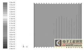
Figure 3 Temperature distribution of radiator fins
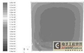
Figure 4 Temperature distribution of the bottom surface of the heat sink substrate
1.2 Experimental Analysis
In order to ensure the reliability of the mathematical model, meshing, calculation method and boundary conditions selected for numerical calculation, we conducted experimental research. The experimental measurement process was carried out in an undisturbed closed space. The experimental system diagram is shown in Figure 5. In the test, the bottom surface of the radiator substrate was covered with an electric heating plate to simulate the heat generated by the LED light group. Thermal conductive silicone grease was filled between the substrate and the electric heating plate to isolate the air thermal resistance. Asbestos board was used to insulate the bottom of the electric heating plate so that all the heat generated by the electric heating plate was dissipated by the radiator.
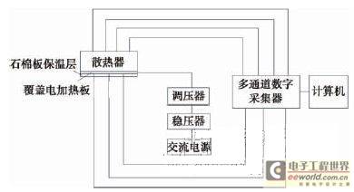
Figure 5 Schematic diagram of the experimental system
In order to reduce the influence of the convection field during the experiment, the thermocouples were led out from the top of the radiator. In order to measure the solid surface temperature of the main part of the radiator, a total of 17 thermocouple measurement points were arranged on the radiator. Among them, thermocouples No. 1 and No. 2 were arranged at the bottom and top of the ribs at the geometric center of the radiator, thermocouples No. 3 and No. 4 were arranged at the bottom and top of the ribs on the front end face of the middle fin of the radiator, thermocouples No. 5 and No. 6 were arranged at the bottom and top of the ribs in the middle of the third rib from the left of the radiator, thermocouples No. 7 and No. 8 were arranged at the bottom and top of the ribs on the front end face of the third rib from the left of the radiator, and thermocouples No. 9 and No. 10 were arranged at the bottom and top of the ribs in the middle section of the outermost rib on the left of the radiator. Thermocouples No. 11 to No. 17 were arranged symmetrically along the symmetry line of the bottom surface of the substrate. The electric heating plate was powered by a voltage stabilizer and a voltage regulator. When the maximum temperature of the bottom surface of the radiator substrate changed within 10 minutes within a range of less than about 0.5℃, we believed that the heating amount of the electric heating plate and the heat dissipation of the radiator were balanced. Afterwards, the temperature values at each measuring point are acquired.
1.3 Comparative analysis of numerical calculation and experimental results
In this paper, the experimental heating power interval is 20W, and the experiment is carried out in the range of 30 to 110W. The maximum temperatures of the bottom surface of the substrate are 41, 55, 67, 78 and 87°C respectively. The corresponding maximum temperatures of the bottom surface of the substrate in numerical calculation are 41, 53, 65, 75 and 88°C respectively. From the experimental and numerical calculation results, it can be seen that with the increase of heating power, the maximum temperature of the bottom surface of the substrate of the radiator also increases, and changes linearly. The comparison of the experimental results and the numerical calculation results is shown in Figure 6. The relative error rate is within 1%, indicating that the numerical analysis results are reliable.
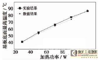
Figure 6 Comparison of experimental results and numerical results 2 Analysis of natural convection process of radiator
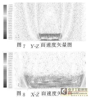
During the natural convection process of the radiator, the bottom surface of the substrate continuously provides heat. Due to the good thermal conductivity of the radiator material, the heat causes the temperature of the radiator to continue to rise. The air around the radiator is heated, and its density decreases, forming a density difference with the air far away from the radiator, generating buoyancy. During the heat dissipation process, the numerical calculation results can obtain the velocity vector field in the YZ plane as shown in Figure 7. It can be seen intuitively that when the air is cooled by the buoyancy of the bottom surface of the radiator substrate, the air directly moves upward from the surrounding of the radiator, but cannot enter the radiator fins to cool the radiator. When the heating amount of the electric heating plate is balanced with the heat dissipation of the radiator, the radiator fins become isothermal wall surfaces. The velocity is caused by the temperature difference. The low velocity causes the buoyancy force of the air to be less than the viscosity force. The cold air around the radiator moves upward from the surrounding of the radiator, and when it finally mixes together, a large stagnant area is formed above the radiator fins. From the velocity vector diagram of the XZ plane in Figure 8, it can be seen that two small vortices are formed at both ends of the stagnant area in the fin direction, preventing the surrounding air from entering the radiator fins. Also, due to the effect of viscous force, the air velocity in this stagnant area is very small, so under such a structure, the fins of the radiator cannot fully exert the heat dissipation effect of natural convection.
3. Improvement of radiator structure
The heat dissipation intensity of natural convection depends not only on the flow rate, temperature difference and fluid properties, but also on the coordination of velocity field and temperature field. From the analysis of numerical calculation results, there are two ways to improve the heat dissipation capacity of the radiator and reduce the maximum temperature of the bottom surface of the substrate: (1) Make the radiator larger. The larger the volume of the radiator, the larger its heat capacity and the larger its heat dissipation area, which is equivalent to reducing the unit heat flux density. However, the disadvantage is that it increases the cost and wastes metal materials; (2) By changing the air turbulence flow field line, the coordination of the velocity field and the temperature field is better. The original radiator model is processed as shown in Figure 9, so that the air can flow up and down in the middle of the radiator under the action of buoyancy, and the turbulence ribs are used to increase the air turbulence area. This not only destroys the stagnant area on the radiator, but also increases the air circulation and cools the radiator more fully.
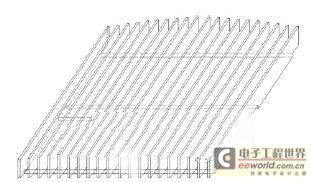
Figure 9 Schematic diagram of the new radiator structure
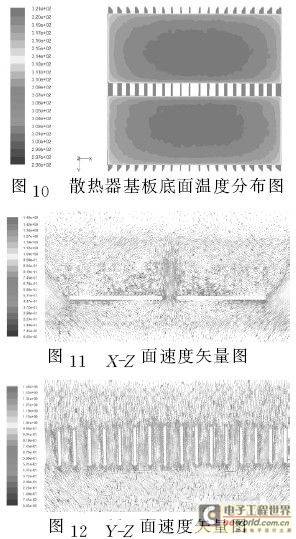
In order to analyze the heat dissipation capacity of the new structure radiator, the comparative experiment verified the reliability of numerical calculation, so we used the same mathematical model, mesh division, calculation method and boundary conditions for numerical calculation and analysis, which is time-saving, efficient and low-cost. The calculation results show that the temperature distribution diagram of the bottom surface of the substrate of the new structure of the radiator is shown in Figure 10. Under the same power, although the heating area of the bottom surface of the substrate is reduced, the unit heat flux density of the bottom surface is increased. However, the maximum temperature of the bottom surface of the substrate of the radiator is still 5°C lower than that of the original model. The average heat transfer coefficient of the fins is also increased from 5.1W/(m2·K) to 6.0W/(m2·K). From the velocity vector diagrams 11 and 12 on the XZ and YZ surfaces, it can be seen that the new structure realizes the up and down circulation of air in the middle of the radiator, increases the air circulation, and the maximum speed of the heated air when it disturbs the fins in the middle of the radiator is only about 0.9m/s. Under this new structure, when the working environment is in windy conditions, the heat exchange effect will be further enhanced, making the heat dissipation effect better. This new structure has a simple processing procedure, reduces the weight of the radiator and the total metal consumption, and is also convenient for automated production and installation.
4 Conclusion
本文运用Fluent软件对大功率LED路灯散热器在大空间中自然对流冷却进行了耦合数值计算。对其散热过程进行了分析,得出了如下结论:(1)数值计算结果与实验结果吻合较好,说明本文计算方法的可靠性;(2)数值计算比实验能更好、更科学、更方便地分析散热器的散热过程;(3)本文设计的散热器新结构,让空气在散热器中间实现上下流通,增加空气流通量,降低了基板底面温度,提高了肋片平均换热系数;(4)底面加工间距对散热器散热能力有显著影响。
Previous article:How to solve the problem of LED heat dissipation
Next article:Discussion on the (green) application technology of LED modern lighting
- Popular Resources
- Popular amplifiers
- MathWorks and NXP Collaborate to Launch Model-Based Design Toolbox for Battery Management Systems
- STMicroelectronics' advanced galvanically isolated gate driver STGAP3S provides flexible protection for IGBTs and SiC MOSFETs
- New diaphragm-free solid-state lithium battery technology is launched: the distance between the positive and negative electrodes is less than 0.000001 meters
- [“Source” Observe the Autumn Series] Application and testing of the next generation of semiconductor gallium oxide device photodetectors
- 采用自主设计封装,绝缘电阻显著提高!ROHM开发出更高电压xEV系统的SiC肖特基势垒二极管
- Will GaN replace SiC? PI's disruptive 1700V InnoMux2 is here to demonstrate
- From Isolation to the Third and a Half Generation: Understanding Naxinwei's Gate Driver IC in One Article
- The appeal of 48 V technology: importance, benefits and key factors in system-level applications
- Important breakthrough in recycling of used lithium-ion batteries
- LED chemical incompatibility test to see which chemicals LEDs can be used with
- Application of ARM9 hardware coprocessor on WinCE embedded motherboard
- What are the key points for selecting rotor flowmeter?
- LM317 high power charger circuit
- A brief analysis of Embest's application and development of embedded medical devices
- Single-phase RC protection circuit
- stm32 PVD programmable voltage monitor
- Introduction and measurement of edge trigger and level trigger of 51 single chip microcomputer
- Improved design of Linux system software shell protection technology
- What to do if the ABB robot protection device stops
- Huawei's Strategic Department Director Gai Gang: The cumulative installed base of open source Euler operating system exceeds 10 million sets
- Download from the Internet--ARM Getting Started Notes
- Learn ARM development(22)
- Learn ARM development(21)
- Learn ARM development(20)
- Learn ARM development(19)
- Learn ARM development(14)
- Learn ARM development(15)
- Analysis of the application of several common contact parts in high-voltage connectors of new energy vehicles
- Wiring harness durability test and contact voltage drop test method
- [NXP Rapid IoT Review] Hello Phased Experience
- STM32F103 and MM32F103 experience
- A radio that can "hear" its own voice
- SPI ASF issue on Atmel ATSAM3X8E
- TouchGFX Design + Make a Rubik's Cube (2)
- To achieve the amplification of weak current, the choice of operational amplifier is the key. Generally, it is selected according to the following situations.
- Electronic digital alarm clock based on GD32E231
- New version of UFUN learning board information
- Mixer Information
- KiCAD 6 is about to be released, and a great guy has made a comparison with 5

 A 40 V 10 W 93%-Efficiency Current-Accuracy- Enhanced Dimmable LED Driver...


 京公网安备 11010802033920号