Introduction
In theory, the power supply rejection ratio (PSRR) measurement is relatively simple. A variable frequency signal modulates the power supply input, and the attenuation of that signal is measured at the output. However, this measurement is highly sensitive to setup noise, including noise from the probing loop area and printed circuit board (PCB) layout. This article explores some common setup issues that limit PSRR measurements and presents a method to overcome these issues using a high-fidelity signal injector and a highly sensitive/selective vector network analyzer (VNA).
Input Signal Modulation
The simplest way to modulate the input to the regulator is to use a line injector such as the Picotest J2120A. This device accommodates 50V input voltage and 5A input current. When used in conjunction with a VNA, the J2120A modulates the input voltage directly and the VNA measures the input/output attenuation. The disadvantages of this method are that the input line needs to be interrupted and the voltage drop of the injector needs to be accommodated. These disadvantages are generally not a problem for laboratory testing, but they can become a problem when measuring in-circuit.
An alternative method to modulate the input is to capacitively connect the VNA to the device under test using a low frequency DC block, such as the J2130A DC bias injector. The magnitude of the signal at the input is limited by the VNA's 50Ω source impedance, but the signal is generally large enough for the VNA to measure. This method does not require interrupting the input connection and can be performed in-circuit without adding any DC loading to the modulated voltage bus.
Calibration
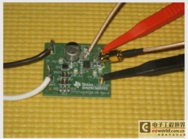
Before making PSRR measurements, it is important to perform a calibration to see if there are any probing variations. It is also important to measure the noise floor of the setup to determine the measurement limits. The photo in Figure 1 shows this test board setup for calibration. The black and white wires are the inputs to the J2120A line injector. The red and black clips on the right are connected to a J2111A current injector (which acts as a 25mA load). Both probes are connected to a common output ground, and both probe tips are connected to the same input so that they have the same modulated signal. A THRU calibration is then performed on the VNA to correct for probe or cable related imperfections. A flat gain response should be seen on the VNA over the frequency band of interest.
Figure 1 THRU calibration test circuit board setup
Noise Floor Evaluation
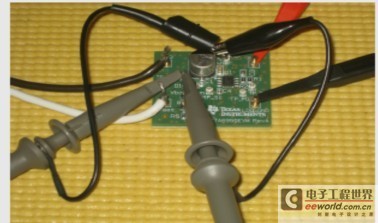
After the probe calibration was completed, the noise floor was evaluated by shorting the output sense probe to the ground connection (Figure 2). From this measurement, it is clear that the noise floor is too high for the PSRR of most regulators today and requires a better setup to find out the actual PSRR. In summary, high-fidelity measurements such as PSRR must use carefully terminated connection points and minimize the probe loop area. In fact, most of the low-fidelity measurements shown in Figure 2 are generated by the noise in the wire loop formed by the oscilloscope probe ground clip.
In the next measurement setup (shown in Figure 3), a 50Ω coaxial line is used in place of the output oscilloscope probe, and an SMA adapter is soldered directly to the output capacitor. The cable is connected to the VNA through a J2130A DC block and a J2102A common-mode transformer. The output ground probe is shorted to evaluate the noise floor. From Figure 3, it is clear that the noise floor is improved by more than 90dB at 1kHz. However, Texas Instruments (TI) has the quietest power regulator with good PSRR above 1MHz, so this noise floor is still unacceptable.
Figure 2. Noise floor measurement using an oscilloscope probe setup.

Figure 3. Noise floor measurement using a 50 Ω coaxial cable instead of the output oscilloscope probe.

Next, the scope probe at the input was replaced with a 50Ω coaxial cable soldered directly to the input capacitor (Figure 4). The complete setup (two 50Ω coaxial cables and J2102A, J2130A, J2120A, and J2111A) and the noise floor/PSRR measurement are shown in Figure 5. This setup has a much lower noise floor, which helps the PSRR measurement reach 1MHz and achieves a low-frequency PSRR of 90dB. The PSRR resonance around 30kHz may be the result of PCB layout or component parasitic interactions.
Figure 4: 50 Ω coaxial cable replaces the input oscilloscope probe

Figure 5. Complete setup and noise floor/PSRR measurement

To illustrate the importance of a good setup, Figure 6 shows the PSRR of a well-designed regulator, PCB layout, and setup. This measurement shows that with a well-designed setup and the right measurement equipment, it is possible to achieve a very low noise floor, allowing for highly accurate PSRR measurements. Finally, to validate the injection methods described above, the PSRR of TI’s LM317 adjustable regulator was measured using a J2120A line injector (method 1) and a J2130A DC bias injector (method 2). Figure 7 shows a nearly perfect overlay, which means very good calibration between the two injection methods.
Figure 6 High-fidelity PSRR and noise floor measurements after optimization
Figure 7. PSRR measurement of LM317 using J2120A and J2130A
Conclusion
This article has shown that, although PSRR measurements are simple in concept, the quality of the setup is extremely important to obtain accurate results. We have also shown methods to lower the noise floor.
Reference
1. “TI LDO Application Notes Title Index” by Masashi Nogawa, see Application Report, available at www.ti.com/sbva026-aaj
Related Websites
Power Management:
www.ti.com/power-aaj
www.ti.com/lm317-aaj
Analog Applications Journal Subscription:
www.ti.com/subscribe-aaj
Previous article:Photoelectric conversion devices: lighting becomes the power source for small appliances
Next article:Design of Current Sense Circuit for Current Mode Control DC/DC Converter
- Popular Resources
- Popular amplifiers
- MathWorks and NXP Collaborate to Launch Model-Based Design Toolbox for Battery Management Systems
- STMicroelectronics' advanced galvanically isolated gate driver STGAP3S provides flexible protection for IGBTs and SiC MOSFETs
- New diaphragm-free solid-state lithium battery technology is launched: the distance between the positive and negative electrodes is less than 0.000001 meters
- [“Source” Observe the Autumn Series] Application and testing of the next generation of semiconductor gallium oxide device photodetectors
- 采用自主设计封装,绝缘电阻显著提高!ROHM开发出更高电压xEV系统的SiC肖特基势垒二极管
- Will GaN replace SiC? PI's disruptive 1700V InnoMux2 is here to demonstrate
- From Isolation to the Third and a Half Generation: Understanding Naxinwei's Gate Driver IC in One Article
- The appeal of 48 V technology: importance, benefits and key factors in system-level applications
- Important breakthrough in recycling of used lithium-ion batteries
- Innolux's intelligent steer-by-wire solution makes cars smarter and safer
- 8051 MCU - Parity Check
- How to efficiently balance the sensitivity of tactile sensing interfaces
- What should I do if the servo motor shakes? What causes the servo motor to shake quickly?
- 【Brushless Motor】Analysis of three-phase BLDC motor and sharing of two popular development boards
- Midea Industrial Technology's subsidiaries Clou Electronics and Hekang New Energy jointly appeared at the Munich Battery Energy Storage Exhibition and Solar Energy Exhibition
- Guoxin Sichen | Application of ferroelectric memory PB85RS2MC in power battery management, with a capacity of 2M
- Analysis of common faults of frequency converter
- In a head-on competition with Qualcomm, what kind of cockpit products has Intel come up with?
- Dalian Rongke's all-vanadium liquid flow battery energy storage equipment industrialization project has entered the sprint stage before production
- Allegro MicroSystems Introduces Advanced Magnetic and Inductive Position Sensing Solutions at Electronica 2024
- Car key in the left hand, liveness detection radar in the right hand, UWB is imperative for cars!
- After a decade of rapid development, domestic CIS has entered the market
- Aegis Dagger Battery + Thor EM-i Super Hybrid, Geely New Energy has thrown out two "king bombs"
- A brief discussion on functional safety - fault, error, and failure
- In the smart car 2.0 cycle, these core industry chains are facing major opportunities!
- The United States and Japan are developing new batteries. CATL faces challenges? How should China's new energy battery industry respond?
- Murata launches high-precision 6-axis inertial sensor for automobiles
- Ford patents pre-charge alarm to help save costs and respond to emergencies
- New real-time microcontroller system from Texas Instruments enables smarter processing in automotive and industrial applications
- GD32L233C-START evaluates the implementation of serial port USART0 printf redirection
- DSP has a problem with printf function running away in CCS environment
- USB transformation of ESP32-S2-Saola-1
- Is there any delay when directly connecting FPGA I/O pins?
- Evaluation Weekly Report 20220207: How many days are left to apply for Qinheng ch582 and Pingtouge Linux RISC-V kit
- About Modbus slave response packet address
- ESD resistance of capacitors
- Date in spring + small flowers blooming in the spring bushes
- [Sipeed LicheeRV 86 Panel Review] Debian Python + Serial Communication
- What is the 5G battle about?


 TC52N5034ECTRT


 京公网安备 11010802033920号