The traditional constant current control of LED lamps is through AC/DC, and then through the DC/DC converter for constant current control. In the AC/DC converter, a filter capacitor is usually used after the rectifier circuit to smooth the output voltage, but the presence of large capacitors causes the input current waveform at the AC end to become a sharp pulse, rather than a sine function (reducing the power factor). Based on the above defects in LED control, this article uses ACLED converter control. In the DC LED converter, since the input power is pulsating and the output power is constant, an intermediate energy storage capacitor is required to balance the difference between the two. Therefore, the energy storage capacitor is generally large in value and uses an electrolytic capacitor. However, the life of the high-value electrolytic capacitor is much shorter than the life of the LED, resulting in a reduction in the life of the overall converter.
If AC LED is used, the input and output power are both pulsating, and the required energy storage capacitor value is smaller, which will increase the life of the overall converter. The existing AC LED lamp circuit structures include series structure, ladder structure and bridge structure. In the AC LED circuit structure, when the input AC source is a grid voltage of 220 V, 50 Hz, if the current limiting resistor is not connected in series, a large number of LED lamps need to be connected in series to limit the LED current. At this time, the total turn-on voltage is increased, resulting in a very low power factor. When the current limiting resistor is connected in series, the number of LEDs required to be connected in series is reduced, and the power factor is improved, but the efficiency will be reduced due to the current limiting resistor. In addition, when the LED operating frequency is 50 Hz, the light source will obviously flicker; when the operating frequency is 100 Hz, most people cannot feel the flickering of the light. In order to solve the low power factor and efficiency of AC LED, and to increase the frequency shown in the load structure, this paper proposes a new AC LED converter topology circuit, and analyzes and studies the topology circuit and control method.
1 Transformation structure of AC LED lamp
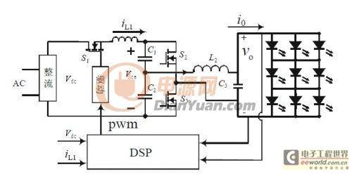
Figure 1 is the structure diagram of the proposed AC LED converter. vdc is the pulsating voltage of 220 V AC voltage after uncontrolled rectification. In order to improve the power factor, this paper adopts Buck PFC circuit to correct the current waveform. The output voltage of Buck PFC circuit is converted into AC signal through half-bridge converter, which is provided to the load LED lamp as the input voltage of the subsequent LCC circuit. Therefore, the topology circuit mainly includes rectification circuit, Buck PFC, half-bridge converter and LCC resonant circuit. As can be seen from Figure 1, the values of C1 and C2 are very small, so the capacitor has no effect on the life of the entire topology circuit; the fundamental frequency of the input and output AC voltage of LCC resonant circuit is 100 Hz, so the voltage frequency of load LED is also 100 Hz, and the voltage flicker cannot be seen at this frequency.
Figure 1 New AC LED converter 1.1 Buck PFC circuit parameter settings
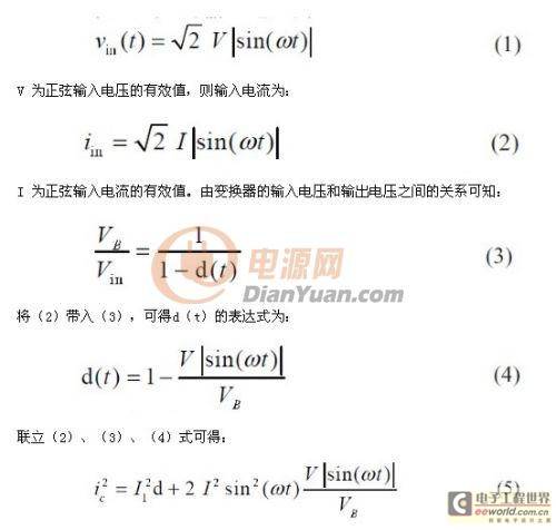
In Figure 1, if the rectified input voltage is:
So the effective value of the capacitor ripple current is:
First, the main switch frequency is set to fs1 = 16.6 kHZ. Because the electrolytic capacitor affects the service life of the converter, the energy storage capacitors C1 and C2 are as small as possible, and C1 = C2 = 1 mF. When the inductor current works in continuous conduction mode (CCM mode), the current ripple size is:
Where: D is the duty cycle of the switch tube S1, and D = Vce/Vdc in CCM mode. Considering that the maximum value of Vdc is 310 V, according to the output voltage limit of the Buck PFC circuit, the peak value of Vce should not exceed 220 V, and the maximum value of the inductor current ripple ΔI L1 is set not to exceed 4A, the optimal reference value of L1 is:
Considering that Buck PFC can operate in discontinuous conduction mode (DCM), the value of inductor L1 can be 0.865 mH. 1.2 Selection of LCC parameters
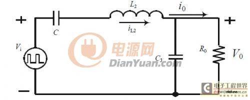
Next, we analyze the calculation method of LCC parameters. By complementary conduction of switch tubes S2 and S3, the input of the LCC resonant circuit is AC, and the working state is shown in Figure 2.
Figure 2 LCC equivalent circuit
According to its working state, the LCC equivalent circuit can be obtained, where C=2 C1=2 C2, and the LED is replaced by its equivalent model.
Von is the series turn-on voltage of 23.5V, and Re is the series equivalent resistance of 7Ω. When the absolute value of the output voltage Vo is less than the turn-on voltage Von, io=0, which is equivalent to no-load condition, and the input-output transfer function is:
According to the load characteristics, when |Vo|
When the absolute value of the output voltage Vo is greater than the turn-on voltage Von, and it is hoped that the change speed of Vo will slow down so that the LED will continue to be turned on, the gain of the input-output transfer function is also required. The gain value must be high enough so that the output voltage can reach the maximum voltage value that the LED can withstand. That is:
Where: Vomax is the peak value of the output voltage, Vimax is the maximum value of |Vcc/2|. Combining equations (10) to (12), it can be obtained that under the condition of satisfying equation (13), according to the restriction condition of equation S95H, the inductor L2 can be selected to be less than 0.45mH.
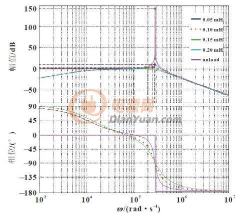
Our design goal is to output power of 20W and the maximum output peak voltage does not exceed 34V. The start-up voltage of each LED string is 23.5V, the equivalent internal resistance is 7Ω, and the maximum peak current does not exceed 1.5A. Therefore, the inductor r6 values are selected as 50, 100, 150, and 200uH to obtain the simulation waveform of Figure 3. According to the gain and resonant frequency constraints, L2=100uH is selected, and C2=133nF can be obtained from formula (12).
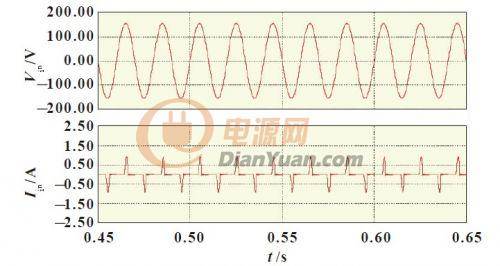
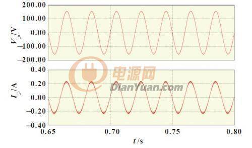
Figure 3 Bode diagram of input-output transfer function under load Through the above theoretical analysis, we simulated and analyzed the circuit without PFC correction circuit and the circuit with PFC correction circuit in Figure 1, as shown in Figure 4 and Figure 5. Through simulation analysis, it can be seen that the topological circuit structure and parameter selection of Figure 1 are feasible.
Figure 4: Simulated waveforms of input AC voltage and AC current without PFC
Figure 5: Input AC voltage and AC current simulation waveforms with PFC
2 Experimental verification
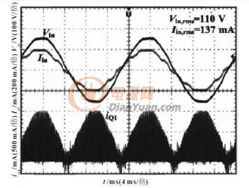
According to the previous theoretical analysis, we made the control module of AC LED lamp, and its design parameters are based on simulation data. The input AC voltage Vin is 220V, the switching frequency of S1 is 20 kHz, and the switching frequency of S2 and S3 is 30 kHz; the main power inductor L1 is 0.865 mH; the resonant inductor L2 is 0.1 mH, the energy storage capacitors C1 and C2 are both 1.2 mF; the resonant capacitor C3 is 133 nF, and the PWM signal of the switch tube is generated by DSP. Figure 6 shows the AC voltage and AC current test waveforms at the power input end when there is no PFC circuit in Figure 1, and Figure 7 shows the AC voltage and AC current test waveforms at the power input end when there is a PFC circuit.
Figure 6 Input voltage Vin and input current iin waveforms without PFC circuit
Figure 7 Input voltage Vin and input current iin waveforms with PFC circuit
3 Conclusion
This paper proposes a new AC LED converter topology circuit to solve the problem that the filter capacitor of the traditional LED lamp rectifier circuit turns the AC input current waveform at the front end of the rectifier into a sharp pulse, resulting in low power factor and increased harmonic components. Through theoretical analysis of the new topology circuit in Figure 1, the capacitance value in the LCC circuit is small, which solves the problem of short service life of LED caused by the large capacitance of the traditional rectifier circuit. This paper also theoretically analyzes the selection of Buck PFC circuit parameter values, simulates and analyzes the phase relationship between the input voltage and current with and without power factor correction circuits, and finally verifies the feasibility of the new circuit topology structure proposed in this paper through experiments.
Previous article:Design of a new high-power blue LED light source drive circuit
Next article:Simple and interesting DIY method of LED car expression instrument
Recommended ReadingLatest update time:2024-11-16 17:53


- MathWorks and NXP Collaborate to Launch Model-Based Design Toolbox for Battery Management Systems
- STMicroelectronics' advanced galvanically isolated gate driver STGAP3S provides flexible protection for IGBTs and SiC MOSFETs
- New diaphragm-free solid-state lithium battery technology is launched: the distance between the positive and negative electrodes is less than 0.000001 meters
- [“Source” Observe the Autumn Series] Application and testing of the next generation of semiconductor gallium oxide device photodetectors
- 采用自主设计封装,绝缘电阻显著提高!ROHM开发出更高电压xEV系统的SiC肖特基势垒二极管
- Will GaN replace SiC? PI's disruptive 1700V InnoMux2 is here to demonstrate
- From Isolation to the Third and a Half Generation: Understanding Naxinwei's Gate Driver IC in One Article
- The appeal of 48 V technology: importance, benefits and key factors in system-level applications
- Important breakthrough in recycling of used lithium-ion batteries
- Innolux's intelligent steer-by-wire solution makes cars smarter and safer
- 8051 MCU - Parity Check
- How to efficiently balance the sensitivity of tactile sensing interfaces
- What should I do if the servo motor shakes? What causes the servo motor to shake quickly?
- 【Brushless Motor】Analysis of three-phase BLDC motor and sharing of two popular development boards
- Midea Industrial Technology's subsidiaries Clou Electronics and Hekang New Energy jointly appeared at the Munich Battery Energy Storage Exhibition and Solar Energy Exhibition
- Guoxin Sichen | Application of ferroelectric memory PB85RS2MC in power battery management, with a capacity of 2M
- Analysis of common faults of frequency converter
- In a head-on competition with Qualcomm, what kind of cockpit products has Intel come up with?
- Dalian Rongke's all-vanadium liquid flow battery energy storage equipment industrialization project has entered the sprint stage before production
- Allegro MicroSystems Introduces Advanced Magnetic and Inductive Position Sensing Solutions at Electronica 2024
- Car key in the left hand, liveness detection radar in the right hand, UWB is imperative for cars!
- After a decade of rapid development, domestic CIS has entered the market
- Aegis Dagger Battery + Thor EM-i Super Hybrid, Geely New Energy has thrown out two "king bombs"
- A brief discussion on functional safety - fault, error, and failure
- In the smart car 2.0 cycle, these core industry chains are facing major opportunities!
- The United States and Japan are developing new batteries. CATL faces challenges? How should China's new energy battery industry respond?
- Murata launches high-precision 6-axis inertial sensor for automobiles
- Ford patents pre-charge alarm to help save costs and respond to emergencies
- New real-time microcontroller system from Texas Instruments enables smarter processing in automotive and industrial applications








 Siemens PLC Project Tutorial
 LED Cube Code


 京公网安备 11010802033920号