One of the challenges for LED lamp designers is to create lighting systems that produce constant light output without noticeable flicker. In systems using single-stage LED drivers , flicker-free lighting is difficult to achieve because random distortion of the line voltage causes the LED current to fluctuate, producing flicker. The circuit feedback response is often the root cause of the problem because it may not react quickly enough to the distortion.
To address this problem, we designed a 7.8W LED system and experimented with a power factor correction (PFC) control circuit. We found that a combination of the two - using an internally generated sinusoidal reference and discontinuous conduction mode (DCM) operation - improved performance, reduced component count, and eliminated flicker.
Internally generated digital sine reference
In most designs that use current-mode operation to control PFC, a sinusoidal reference is obtained by sensing the input voltage using a resistor divider. An internally generated sinusoidal reference, which is generated using digital mapping, can make the LED current more stable in a buck-boost topology. An internally generated sinusoidal reference can also eliminate the resistor divider, resulting in a lower component count and more compact design. Figure 1 provides a block diagram of the circuit.
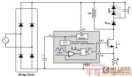
Figure 1. LED driver configuration
The power supply voltage (Vcc) is supplied by the high voltage (HV) device built into the controller. Because the input voltage zero-crossing trigger is detected by the Vcc and HV blocks, the internal sine reference and the zero-crossing trigger signal are synchronized. The output signal from the on-chip digital-to-analog converter (DAC) generates a digital sine reference using the internally mapped sine information and the synchronized zero-crossing trigger signal. When the Vcc voltage is less than 15.5V, the voltage of the zero-crossing trigger detector (ZCD) is low and the DAC and the internal clock automatically provide a digital reference signal with a digital step of 32 bits.
CRM and DCM Operations
In converters using boost topology, the input current is configured by the inductor current. Since there is a constant on-time and variable off-time, this optimizes PFC in critical conduction mode (CRM) operation. On the other hand, with the buck-boost topology, the input current is proportional to the switch current. As a result, PFC is reduced in CRM operation and the line peak voltage becomes flatter. The input current is determined by the inductor current associated with the MOSFET turning on. Equation 1 shows how the input current is calculated in a buck-boost converter.

(Equation 1)
Based on Equation 1, the input current is proportional to the input voltage by controlling the constant on-time and constant switching period in the buck-boost converter. This means that the best approach is discontinuous conduction mode (DCM) operation with a fixed on-time. Constant Current Line Regulation
As mentioned above, to improve LED current fluctuation and line voltage distortion, our design uses DCM operation and a fixed internal sinusoidal reference in the buck-boost converter. This approach does a better job of regulating the LED current, and it has no noticeable flicker even when there are line voltage transients between 90Vac and 265Vac. Figure 2 shows the current slope of the inductor current.
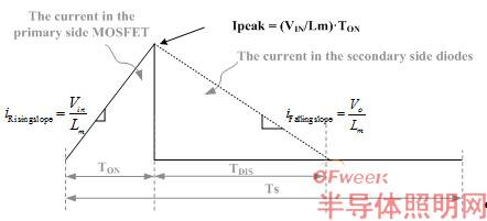
Figure 2. Current slope of inductor current
Based on the results of Figure 2, the output current can be calculated using Equation 2.

(Equation 2)
In Equation 2, the output current is not a function of the input voltage because the peak value of the fixed sinusoidal I is controlled by the internal reference. Figure 3 shows the line regulation for constant current.
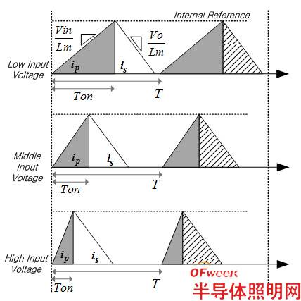
Figure 3. Constant current line regulation
As the input voltage changes, the LED current is constantly regulated by a fixed I peak and a fixed inductor current falling slope. Constant Power Load Regulation
Using the proposed LED driving method, the output current is not constantly regulated when the output voltage changes. Equation 3 is derived from Equation 2, which shows the output power calculation.

(Equation 3)
Because Ipeak and Ts are fixed by the controller, the output current decreases and the output power is continuously regulated as the output voltage increases.
Regulation: Line and Load
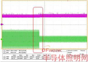
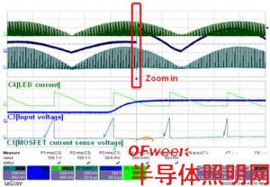
Typically line regulation is used to adjust the output current in response to input voltage changes. Load regulation is used to maintain output power regardless of changes in the LED forward voltage. Constant current load regulation is used to reduce LED power and reduce light emission as the forward voltage drops in response to system temperature or LED derating. Figure 4 shows the line voltage distortion caused by input voltage changes from (a) 90Vac to 265Vac, (b) 265Vac to 90Vac, and (c) 200Vac to 400Vac.
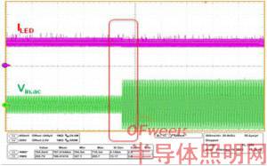
(a) Input voltage changes from 90Vac to 265Vac
(b) Input voltage changes from 265Vac to 90Vac
(c) Input voltage changes from 200Vac to 400Vac
Figure 4. Line voltage distortion
in conclusion
The buck-boost LED driver combination using a fixed sinusoidal reference in DAC and DCM mode has a fixed frequency and can help reduce flicker. The internally generated sinusoidal reference greatly reduces the LED current when the line voltage has random variations. In addition, the design provides more continuous brightness and constant power load regulation because current mode control uses temperature or LED derating to compensate for the LED.
Author : Gwanbon Koo, Taesung Kim, Fairchild Semiconductor
Previous article:7.8W LED system reduces component count and eliminates LED flicker
Next article:In-depth analysis of high-power LED lamp cooling fan detection circuit
- Popular Resources
- Popular amplifiers
- MathWorks and NXP Collaborate to Launch Model-Based Design Toolbox for Battery Management Systems
- STMicroelectronics' advanced galvanically isolated gate driver STGAP3S provides flexible protection for IGBTs and SiC MOSFETs
- New diaphragm-free solid-state lithium battery technology is launched: the distance between the positive and negative electrodes is less than 0.000001 meters
- [“Source” Observe the Autumn Series] Application and testing of the next generation of semiconductor gallium oxide device photodetectors
- 采用自主设计封装,绝缘电阻显著提高!ROHM开发出更高电压xEV系统的SiC肖特基势垒二极管
- Will GaN replace SiC? PI's disruptive 1700V InnoMux2 is here to demonstrate
- From Isolation to the Third and a Half Generation: Understanding Naxinwei's Gate Driver IC in One Article
- The appeal of 48 V technology: importance, benefits and key factors in system-level applications
- Important breakthrough in recycling of used lithium-ion batteries
- LED chemical incompatibility test to see which chemicals LEDs can be used with
- Application of ARM9 hardware coprocessor on WinCE embedded motherboard
- What are the key points for selecting rotor flowmeter?
- LM317 high power charger circuit
- A brief analysis of Embest's application and development of embedded medical devices
- Single-phase RC protection circuit
- stm32 PVD programmable voltage monitor
- Introduction and measurement of edge trigger and level trigger of 51 single chip microcomputer
- Improved design of Linux system software shell protection technology
- What to do if the ABB robot protection device stops
- Sn-doped CuO nanostructure-based ethanol gas sensor for real-time drunk driving detection in vehicles
- Design considerations for automotive battery wiring harness
- Do you know all the various motors commonly used in automotive electronics?
- What are the functions of the Internet of Vehicles? What are the uses and benefits of the Internet of Vehicles?
- Power Inverter - A critical safety system for electric vehicles
- Analysis of the information security mechanism of AUTOSAR, the automotive embedded software framework
- Brief Analysis of Automotive Ethernet Test Content and Test Methods
- How haptic technology can enhance driving safety
- Let’s talk about the “Three Musketeers” of radar in autonomous driving
- Why software-defined vehicles transform cars from tools into living spaces
- 6678 I am debugging the phy network. If I encounter any problems, please help me. Thank you.
- RSL10 Development Board Circuit Overview
- TI DSP C6000 structural knowledge
- LSD-FET430UIF wiring diagram
- Grab the post! A wave of high-quality tutorials is coming, comment and forward the tutorials to get gifts! Cheer for the 2019 National Competition~
- [N32L43X Review] 5. Hardware SPI driver for OLED
- Methods for reducing board size and battery consumption in low voltage H-bridge applications
- When the LSM6DS3TR-C is configured with the I2C address, the power consumption is high when the SA0 pin is connected to GND.
- Regarding MCU, here are some ideas for R&D!
- [Erha image recognition artificial intelligence visual sensor] 2: Erha visual sensor and host computer serial port communication experiment

 ACA2401S7P0


 京公网安备 11010802033920号