Camera phones are now used as formal digital cameras. Users want to take high-quality photos even in low-light conditions, so an additional illumination source is needed in camera phones. White LEDs are widely used as camera flashes in camera phones. This article discusses in detail the various considerations when designing white LEDs in camera phones. The article describes the series and parallel operation modes of white LED driver circuits, and discusses the specific circuit design method using Avago Technologies' HSMW-C830/C850 flash module as an example.
Today's "standard" camera phones offer a resolution of 640 x 480 pixels for a 300,000-pixel image size. In early 2004, the most advanced camera phones offered 1,600 x 1,200-pixel images - about 2-megapixel images - and the ability to record video clips and use removable memory cards, with autofocus and other camera features integrated in some models. One manufacturer announced a 7-megapixel camera phone for 2005.
The result is that camera phones are now being used as "proper" digital cameras, and consumers expect to be able to take high-quality photos in low-light conditions, so the need to add a light source that will not quickly drain the phone's battery has begun to emerge.
There are two types of flash lamps available for digital cameras: xenon flash tubes and white LEDs. Xenon flash lamps are widely used in film cameras and standalone digital cameras because of their high brightness and white light. Most camera phones, on the other hand, choose white LED lighting. Table 1 compares the two types of flash lamps.
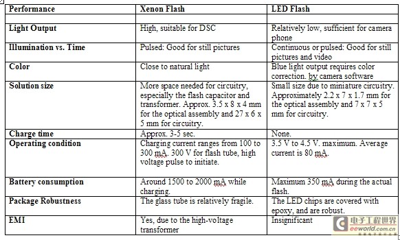
Table 1: Comparison of Xenon Flash and LED Flash
LEDs are current-driven devices whose light output is determined by the forward current passing through them. LEDs can flash faster than any other light source, including xenon flash lamps, which have very short rise times ranging from 10 to 100ns. The lighting quality of white LEDs is now comparable to that of cool white fluorescent lamps, with a color rendering index approaching 85.
In most cases, the maximum light output of an LED is limited by the maximum average forward current it can withstand, which is primarily determined by the power dissipation level of the LED chip/package and the heat dissipation performance of the heat sink to which it is attached. In flash applications, the LED can be driven with pulsed currents with very small duty cycles. This allows the current, and the light output produced by the current, to be significantly increased during the actual pulse, while still keeping the average current level and power dissipation of the LED within its safe ratings.
Compared with xenon flash, LED flash has lower power consumption and the driving circuit takes up very little space. In addition, driving LED flash does not generate much electromagnetic interference (EMI). These advantages have led to the application of LED flash in camera phones. Moreover, the same LED flash can be used as a continuous light source, which makes it useful for video applications as well as flashlight functions.
Selecting LEDs for Camera Phone Flash Applications
Although there are no packaging and electronics standards in the flash LED space, manufacturers have defined many LED components for camera flash applications. When designing an LED flash in a camera phone, the guidelines to consider are:
1. Optical properties;
2. Ease and flexibility of electronic design;
3. Pulse modulation function;
4. Can be effectively cascaded to obtain higher light output;
5. Heat dissipation considerations;
6. Manufacturing and assembly considerations. In particular, the compatibility of the LED module with the manufacturing process used in camera phones.
Optical properties
Most digital camera modules currently used in camera phones have a 50-60° viewing angle and require at least 3 to 5 Lux of brightness to obtain good photos. Therefore, a photo flash with a lighting angle of 50-80° is the best choice. Lighting angles exceeding 80° will cause some light to fall outside the camera coverage area, thereby reducing the utilization of LED light output. Conversely, a flash with a smaller lighting angle may result in dark areas in the corners of the captured photos.
Most LED assemblies for camera flash available on the market today have a wide illumination angle. This angle can be finely adjusted using secondary optics, but these optics have two major drawbacks. First, secondary optics cause approximately 12% light loss due to conversion efficiency; second, using secondary optics increases the cost of camera phones, takes up additional space, and complicates the manufacturing and design process.
In the case of LED flash modules manufactured by Avago Technologies, the curved design focuses the light from the LED into a 60° Lambertian radiation pattern, maximizing the light output intensity that falls within a typical camera's field of view.
Each flash module from Avago Technologies integrates three InGaN LED dies, which are connected in parallel (HSMW-C830) or in series (HSMW-C850) within the module, with each module having only two terminals, cathode and anode. Both methods have their own advantages and disadvantages (Table 2).
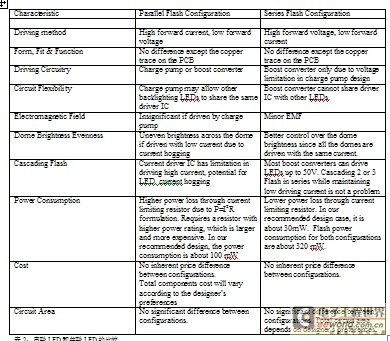
Table 2: Comparison of LEDs in series and in parallel
Easy to cascade and dissipate heat
Avago Technologies designed the HSMW-C830 and HSMW-C850 to be mechanically and electronically cascaded. The package is intentionally thin, so that designers can stack two modules to double the light output, and this combination takes up minimal space. If two modules are stacked vertically, the combined size is only 7.0× 4.4mm2 .
Most LED flash modules use a common anode to connect the LEDs together. Serial cascading of flash modules requires the driver to provide both high current and high voltage, while cascading them in parallel creates a potential problem of light output brightness variation because the current may be unevenly distributed between the two modules. The HSMW-C850 connects all three chips in series. If they are cascaded, only the voltage needs to be adjusted without changing the drive current, so there will be no problem of two modules receiving different currents. In addition, the existing boost converters on the market feature high adaptive voltage and low current drive, rather than high current drive and low adaptive voltage, because this saves overall power consumption.
LED flash modules can generate considerable heat during operation, so heat dissipation measures must be considered during the design-in process. Most mobile phone designers prefer flexible printed circuit boards (which have poor heat dissipation) rather than FR4 PCB materials due to space constraints. Avago Technologies' flash modules have low package thermal resistance and can effectively release the heat generated by the LED. Avago Technologies' flash can illuminate continuously for 5 seconds at a current of 80mA at an ambient temperature of +55°C.
Circuit Design
The lithium-ion battery in a mobile phone is a voltage source, and its output voltage varies with the amount of energy retained (usually between 2.8 and 4.2V). Because LEDs are current-driven devices, they need to be driven by a constant current source to obtain consistent light output. Charge pump converters and voltage boost converters are two possible DC/DC conversion topologies suitable for driving LED flashes.
The necessary length of time for flash illumination is determined by the specific requirements of the specific camera module. As long as the illumination time is not shorter than the imaging time of the module, the photographic effect will not be affected. Generally speaking, an illumination time of 200~300ms is sufficient. Avago Technologies' flash module can drive a current of 180mA with a pulse width of less than 200ms, providing a brightness of 10lux. Under continuous working conditions, the maximum allowable current is 80mA, producing a brightness of approximately 6lux.
Figure 2 shows the HSMW-C830 flash module, with parallel LEDs powered by a TPS60230 charge pump IC.
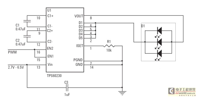
Figure 2: Using a charge pump IC to drive parallel-connected LEDs
By connecting an external resistor (10kΩ) from the ISET pin to ground (GND), a constant current of about 16mA is provided through the D1 to D6 pins. The LED flash draws 78mA. Two 1μF and two 0.47μF external capacitors are required. In addition, the current-controlled charge pump ensures low EMI interference.
Enable pins EN1 and EN2 are used to enable the device (provide 1/3, 2/3, or all of the 78mA current) or set it to shutdown mode, as shown in Table 3.

Table 3: Controlling LED current using the enable pin of the TPS60230 charge pump IC
In shutdown mode, the charge pump, current source and reference voltage, oscillator and all other functions are turned off, reducing the current consumption to 0.1μA.
The logic levels on EN1 and EN2 set the voltage on the ISET pin (VISET) to ground (GND). The current can be set to 26mA, 52mA, or 78mA according to VISET, as shown below. When EN1=0 and EN2=1, then Eq1.
Here, Eq2, hence Eq3. By connecting D1 to D5, this device provides Eq4.
EN1 and EN2 can also be used for pulse width modulation (PWM) to dim the brightness. The PWM signal can be added to EN1 or EN2, or the two pins can be connected together to control the brightness of the LED flash. When using a fully charged battery, this circuit can achieve a power conversion efficiency of more than 85%.
Figure 3 shows the use of the TPS61040 as a boost converter to drive parallel LEDs.
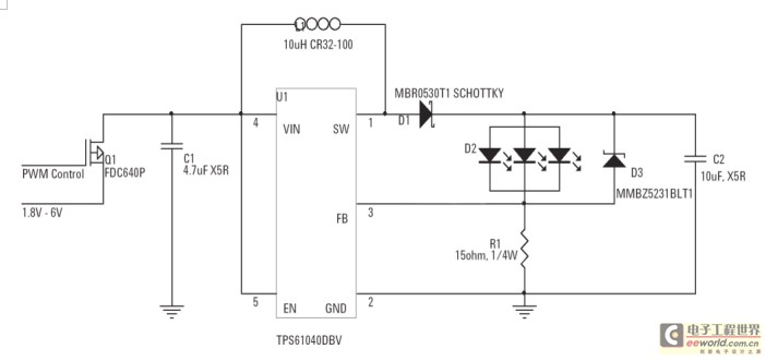
Figure 3: Using a boost converter IC to drive parallel-connected LEDs
By connecting an external 15Ω resistor between the FB pin and GND, the device provides a constant current of 80mA according to the feedback voltage (VFB = 1.233V). Forward Current Eq5 .
This design allows the use of physically smaller external components on the output (using ceramic capacitors instead of tantalum capacitors) due to the high switching frequency of 1MHz provided by the TPS61040. The PWM control pin is used to control the brightness of the flash LED. The circuit can achieve 85% power conversion efficiency.
By changing the values of R1 and D3 (see Figure 4), the boost topology can drive LEDs in series (Avago Technologies HSMW-C850).
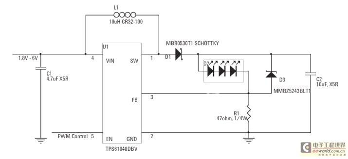
Figure 4: Driving serially connected LEDs using a boost converter IC
Using a 47Ω resistor to ground and a 1.233V reference voltage, the device can deliver 26mA.
Previous article:Buck-boost constant current LED driver design
Next article:Power supply requirements and solutions for OLED display technology
Recommended ReadingLatest update time:2024-11-16 15:25


- Popular Resources
- Popular amplifiers
- MathWorks and NXP Collaborate to Launch Model-Based Design Toolbox for Battery Management Systems
- STMicroelectronics' advanced galvanically isolated gate driver STGAP3S provides flexible protection for IGBTs and SiC MOSFETs
- New diaphragm-free solid-state lithium battery technology is launched: the distance between the positive and negative electrodes is less than 0.000001 meters
- [“Source” Observe the Autumn Series] Application and testing of the next generation of semiconductor gallium oxide device photodetectors
- 采用自主设计封装,绝缘电阻显著提高!ROHM开发出更高电压xEV系统的SiC肖特基势垒二极管
- Will GaN replace SiC? PI's disruptive 1700V InnoMux2 is here to demonstrate
- From Isolation to the Third and a Half Generation: Understanding Naxinwei's Gate Driver IC in One Article
- The appeal of 48 V technology: importance, benefits and key factors in system-level applications
- Important breakthrough in recycling of used lithium-ion batteries
- Innolux's intelligent steer-by-wire solution makes cars smarter and safer
- 8051 MCU - Parity Check
- How to efficiently balance the sensitivity of tactile sensing interfaces
- What should I do if the servo motor shakes? What causes the servo motor to shake quickly?
- 【Brushless Motor】Analysis of three-phase BLDC motor and sharing of two popular development boards
- Midea Industrial Technology's subsidiaries Clou Electronics and Hekang New Energy jointly appeared at the Munich Battery Energy Storage Exhibition and Solar Energy Exhibition
- Guoxin Sichen | Application of ferroelectric memory PB85RS2MC in power battery management, with a capacity of 2M
- Analysis of common faults of frequency converter
- In a head-on competition with Qualcomm, what kind of cockpit products has Intel come up with?
- Dalian Rongke's all-vanadium liquid flow battery energy storage equipment industrialization project has entered the sprint stage before production
- Allegro MicroSystems Introduces Advanced Magnetic and Inductive Position Sensing Solutions at Electronica 2024
- Car key in the left hand, liveness detection radar in the right hand, UWB is imperative for cars!
- After a decade of rapid development, domestic CIS has entered the market
- Aegis Dagger Battery + Thor EM-i Super Hybrid, Geely New Energy has thrown out two "king bombs"
- A brief discussion on functional safety - fault, error, and failure
- In the smart car 2.0 cycle, these core industry chains are facing major opportunities!
- The United States and Japan are developing new batteries. CATL faces challenges? How should China's new energy battery industry respond?
- Murata launches high-precision 6-axis inertial sensor for automobiles
- Ford patents pre-charge alarm to help save costs and respond to emergencies
- New real-time microcontroller system from Texas Instruments enables smarter processing in automotive and industrial applications
- Important network technologies of 5G system
- Start broadcasting at 10:00: Enter the TI robot production classroom and start the journey of deep learning practice! (100% courtesy for invitation viewing)
- Detailed explanation of GPIO input and output modes
- Millimeter wave sensors enable edge intelligence
- A few key points about interrupts
- EEWORLD University - Make your design easier - Get to know TI's latest reference design for motor drive
- 32 MCU reset problem during operation
- Highly reliable medical bubble detection
- [National Competition Interview] “Three weaklings” won the first prize for question H, and the winners who won by luck are here! ?
- Kuyuan Electric Allegro video training

 Siemens PLC Project Tutorial
 LED Cube Code
 ESP32-S3 source code


 京公网安备 11010802033920号