MR16 lamps are a type of multi-faceted reflector lamps that are widely used in commercial retail and home decorative lighting. Since they usually use halogen filaments as light sources, they have many disadvantages such as low efficiency, high heat generation and halogen capsule handling. However, current LED technology provides a halogen lamp alternative that is compatible with MR16, highly reliable and cost-effective. For example, ON Semiconductor's driver CAT4201, which can drive three LEDs in series, provides a new option for engineers designing MR16 LED lamps. The following will combine the characteristics of MR16 lamps to introduce high-efficiency MR16 LED lamp driver solutions that replace MR16 halogen lamps.
Characteristics of halogen lamps and LEDs
MR16 halogen lamps are used in creative lighting for many retail and consumer applications due to their unique size, configurability, focusing ability, aesthetics and practicality. The luminous flux of common MR16 halogen lamps ranges from 150 lumens (lm) to 800 lm, and the luminous efficacy is about 15 lm/W, or 15% luminous efficiency. Low efficiency, heat generation and halogen capsule handling issues are the disadvantages of this technology. In addition, the typical life of a halogen bulb is about 2,000 hours. It is also possible that the filament breaks due to violent vibration, causing the bulb to fail prematurely.
In comparison, LEDs are energy-saving and environmentally friendly, with very low power consumption. The general operating voltage of LEDs is 2 to 3.6 V. LEDs are a cold light-emitting technology that generates much less heat than ordinary lighting sources; LEDs are completely encapsulated in epoxy resin, and there are no loose parts in the lamp body, so they are not easy to damage. Under the appropriate current and voltage, the service life of LEDs can reach 50,000 to 100,000 hours; LEDs are made of non-toxic materials and are pollution-free. The current disadvantage of LEDs is that they are relatively expensive and it is difficult to handle the heat, so the driving power supply is a key factor in the overall life of LED lamps.
Replace inefficient MR16 halogen lamps with LED MR16 lamps
ON Semiconductor's CAT4201 is a 300 mA LED driver that can drive 3 LEDs in series, which can be used in MR-16 LED lamp designs. Because the device has been optimized, it is more perfect in terms of the number of external components and thermal performance.
• Circuit Features
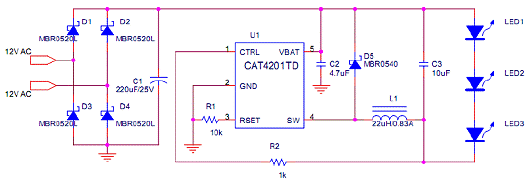
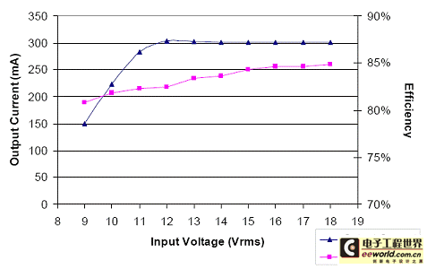
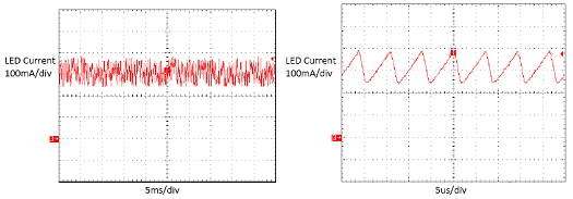
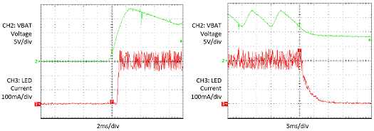
The CAT4201 uses a buck topology and does not require input/output (I/O) electrical isolation. The input voltage is 12 Vac and the output power is 2.7 W. Other specifications include: output voltage is 9.1 V, rated input power is 3.4 W, rated average current is 300 mA, maximum average current is 310 mA, minimum average current is 295 mA, and typical energy efficiency is 83%. Figure 1 is an MR16 lamp circuit using CAT4201. Figure 1: MR16 lamp circuit using CAT4201 The CAT4201 is a step-down, easy-to-configure, dimmable LED driver. The device uses a 5-pin SOT-23 package; with less than 10 discrete components (most of which are surface-mount components), the entire circuit board can be small enough to fit into the lamp holder of an MR16 lamp. The VBAT, CTRL, and SW pins are rated for 40 V, so there is enough voltage to drive 12 LEDs. The RSET pin determines the output DC current; CTRL is used for dimming signal input. SW is the output pin of the internal MOSFET. • Working Principle The working principle of this application circuit is not complicated, it is a simple buck converter. In AC application, the input is rectified by a rectifier bridge. VBAT and GND are directly connected to the two terminals of the large-capacity capacitor C1, which reduces the current ripple. During the first switching phase, the internal MOSFET charges the inductor with a linearly rising current until the MOSFET is turned off; during the second phase, the MOSFET is turned off, and the current stored in the inductor will be discharged through the Schottky diode (D5) while the current decays until the next switching cycle. The output capacitor is used to reduce the current ripple in the LED. The voltage of the RSET pin is regulated at 1.2 V, so the resistor connected to RSET determines the RSET current. The RSET current is roughly proportional to the constant current output of the CAT4201. • Circuit Configuration In terms of circuit configuration, the rated voltage of VBAT is -0.3 to +40 V, so the input voltage on the rectifier bridge is safe up to 24 Vac. A large-capacity C1 is required to maintain a higher input voltage level. The large fluctuations in the rectified AC current will pull the output current to zero at double the AC line frequency, thus reducing the output current. A capacitor of 220 μF is sufficient for this design. For 12 Vac input, C1 should be rated at 25 V. MBR0520L surface mount Schottky diodes were selected for the bridge rectifier due to the need for a lower forward voltage. Output capacitor C2 is recommended to be at least 4.7 μF to reduce output ripple. A larger value of C2 will effectively suppress the output ripple while increasing the output current by a few mA. However, since its contribution to the overall efficiency is negligible and the human eye cannot perceive high frequency fluctuations, it is not necessary to use a capacitor greater than 10 μF. The value of L is recommended to be 22 μH to set the switching frequency at about 150 kHz. The LED current range is 0 to 350 mA, so an effective inductor current rating of about 800 mA is sufficient. The total continuous current flowing through the rectifier is always less than 400 mA, even when an output current of 350 mA is provided. Therefore, a continuous current rating of 0.5 A is sufficient for the rectifier. A closer look at the voltage across the freewheeling diode D5 shows that despite the 12 Vac input, voltage spikes exceeding 20 V occur. Higher input voltages (e.g., 15 V) further stress the diode and increase the risk of failure. Therefore, the rated voltage on D5 should be 30 V or 40 V. ON Semiconductor's Schottky rectifier MBR0540 can be used as D5. The RSET pin is used to configure the output current value. The RSET voltage is regulated at 1.2 V. Adding a resistor between RSET and GND determines the RSET current, which is approximately linear with the output constant voltage: Calculation shows that for 300 mA output, IRSET = 0.12 mA. The RSET resistor value should be 10 kΩ. A smaller RSET resistor may increase the output current, and a resistor of at least 8.0 kΩ is recommended for stable operation. If the input voltage is high enough (e.g., 15 Vac), RSET can be set to 8.2 kΩ, thus ensuring at least 350 mA of output current. CTRL obtains the voltage from the cathode of the LED through R2. The value of R2 is not important. Performance and Features The basic performance and features of the circuit can be understood from the waveforms shown in Figures 2 to 4 below. Its test equipment includes: Global Specialties 1506 AC Isolated Voltage Variable AC Line Power Supply; Voltech PM1000 Power Analyzer; Tektronix TDS754D Digital Phosphor Oscilloscope; Tektronix TCP202 Current Probe; Agilent 34401A Multimeter. Figure 2: Relationship between input voltage, output current and efficiency In the circuit configured according to the circuit diagram of Figure 1, Vin = 12 Vac 50Hz. Due to the AC line input, the LED current has very slight low-frequency (twice the AC frequency, 2 × 50HZ) fluctuations. Using a larger capacity C1 or a higher Vin will further smooth out the AC-related ripple current. Figure 3: LED current waveform In a circuit configured according to the circuit diagram of Figure 1, the startup and power-off transients are shown in Figure 4. Figure 4: Startup and power-off transients Compact design





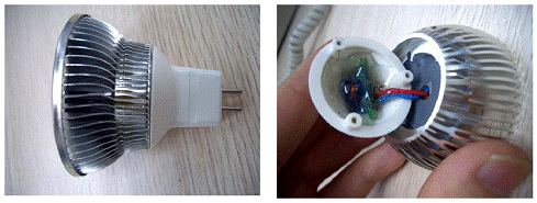
The advantages of the CAT4201 driver are compact circuitry and high efficiency, making it ideal for replacing filament-based bulbs such as spotlight applications. This ultra-small design can fit into the space of a standard connector (lamp holder) for MR16-type LED spotlights, separating these temperature-sensitive components from the hot LEDs as much as possible.
Due to optimization, the design is more perfect in terms of component count and thermal performance. This design can generally use three 1 W LEDs in the mirror part, and can be adjusted to meet the requirements of lighting system designers. In the final solution, the LED current and capacitor size must be traded off to achieve the best energy efficiency, accuracy, size and component count. Figure 5: The micro LED driver board can be embedded in the lamp holder Summary This design provides the various elements required to drive a 3-LED MR-16 lamp using the CAT4201 design. The CAT4201 helps achieve a smaller size and fewer components for MR-16 compatible adapters. Reducing the capacitor and inductor values, or not using the CTRL resistor, has the potential to further reduce cost and PCB size. Using a small capacitor will result in a significant drop in the average output current and is not recommended, but is suitable for lower brightness (200 to 250 mA) applications. Selecting high-quality LEDs with a small forward voltage is important for designs that achieve higher output currents.

Keywords:MR16 LED
Reference address:Simple, Configurable LED Driver Application Design for MR16 LED Lamps
Characteristics of halogen lamps and LEDs
MR16 halogen lamps are used in creative lighting for many retail and consumer applications due to their unique size, configurability, focusing ability, aesthetics and practicality. The luminous flux of common MR16 halogen lamps ranges from 150 lumens (lm) to 800 lm, and the luminous efficacy is about 15 lm/W, or 15% luminous efficiency. Low efficiency, heat generation and halogen capsule handling issues are the disadvantages of this technology. In addition, the typical life of a halogen bulb is about 2,000 hours. It is also possible that the filament breaks due to violent vibration, causing the bulb to fail prematurely.
In comparison, LEDs are energy-saving and environmentally friendly, with very low power consumption. The general operating voltage of LEDs is 2 to 3.6 V. LEDs are a cold light-emitting technology that generates much less heat than ordinary lighting sources; LEDs are completely encapsulated in epoxy resin, and there are no loose parts in the lamp body, so they are not easy to damage. Under the appropriate current and voltage, the service life of LEDs can reach 50,000 to 100,000 hours; LEDs are made of non-toxic materials and are pollution-free. The current disadvantage of LEDs is that they are relatively expensive and it is difficult to handle the heat, so the driving power supply is a key factor in the overall life of LED lamps.
Replace inefficient MR16 halogen lamps with LED MR16 lamps
ON Semiconductor's CAT4201 is a 300 mA LED driver that can drive 3 LEDs in series, which can be used in MR-16 LED lamp designs. Because the device has been optimized, it is more perfect in terms of the number of external components and thermal performance.
• Circuit Features
The CAT4201 uses a buck topology and does not require input/output (I/O) electrical isolation. The input voltage is 12 Vac and the output power is 2.7 W. Other specifications include: output voltage is 9.1 V, rated input power is 3.4 W, rated average current is 300 mA, maximum average current is 310 mA, minimum average current is 295 mA, and typical energy efficiency is 83%. Figure 1 is an MR16 lamp circuit using CAT4201. Figure 1: MR16 lamp circuit using CAT4201 The CAT4201 is a step-down, easy-to-configure, dimmable LED driver. The device uses a 5-pin SOT-23 package; with less than 10 discrete components (most of which are surface-mount components), the entire circuit board can be small enough to fit into the lamp holder of an MR16 lamp. The VBAT, CTRL, and SW pins are rated for 40 V, so there is enough voltage to drive 12 LEDs. The RSET pin determines the output DC current; CTRL is used for dimming signal input. SW is the output pin of the internal MOSFET. • Working Principle The working principle of this application circuit is not complicated, it is a simple buck converter. In AC application, the input is rectified by a rectifier bridge. VBAT and GND are directly connected to the two terminals of the large-capacity capacitor C1, which reduces the current ripple. During the first switching phase, the internal MOSFET charges the inductor with a linearly rising current until the MOSFET is turned off; during the second phase, the MOSFET is turned off, and the current stored in the inductor will be discharged through the Schottky diode (D5) while the current decays until the next switching cycle. The output capacitor is used to reduce the current ripple in the LED. The voltage of the RSET pin is regulated at 1.2 V, so the resistor connected to RSET determines the RSET current. The RSET current is roughly proportional to the constant current output of the CAT4201. • Circuit Configuration In terms of circuit configuration, the rated voltage of VBAT is -0.3 to +40 V, so the input voltage on the rectifier bridge is safe up to 24 Vac. A large-capacity C1 is required to maintain a higher input voltage level. The large fluctuations in the rectified AC current will pull the output current to zero at double the AC line frequency, thus reducing the output current. A capacitor of 220 μF is sufficient for this design. For 12 Vac input, C1 should be rated at 25 V. MBR0520L surface mount Schottky diodes were selected for the bridge rectifier due to the need for a lower forward voltage. Output capacitor C2 is recommended to be at least 4.7 μF to reduce output ripple. A larger value of C2 will effectively suppress the output ripple while increasing the output current by a few mA. However, since its contribution to the overall efficiency is negligible and the human eye cannot perceive high frequency fluctuations, it is not necessary to use a capacitor greater than 10 μF. The value of L is recommended to be 22 μH to set the switching frequency at about 150 kHz. The LED current range is 0 to 350 mA, so an effective inductor current rating of about 800 mA is sufficient. The total continuous current flowing through the rectifier is always less than 400 mA, even when an output current of 350 mA is provided. Therefore, a continuous current rating of 0.5 A is sufficient for the rectifier. A closer look at the voltage across the freewheeling diode D5 shows that despite the 12 Vac input, voltage spikes exceeding 20 V occur. Higher input voltages (e.g., 15 V) further stress the diode and increase the risk of failure. Therefore, the rated voltage on D5 should be 30 V or 40 V. ON Semiconductor's Schottky rectifier MBR0540 can be used as D5. The RSET pin is used to configure the output current value. The RSET voltage is regulated at 1.2 V. Adding a resistor between RSET and GND determines the RSET current, which is approximately linear with the output constant voltage: Calculation shows that for 300 mA output, IRSET = 0.12 mA. The RSET resistor value should be 10 kΩ. A smaller RSET resistor may increase the output current, and a resistor of at least 8.0 kΩ is recommended for stable operation. If the input voltage is high enough (e.g., 15 Vac), RSET can be set to 8.2 kΩ, thus ensuring at least 350 mA of output current. CTRL obtains the voltage from the cathode of the LED through R2. The value of R2 is not important. Performance and Features The basic performance and features of the circuit can be understood from the waveforms shown in Figures 2 to 4 below. Its test equipment includes: Global Specialties 1506 AC Isolated Voltage Variable AC Line Power Supply; Voltech PM1000 Power Analyzer; Tektronix TDS754D Digital Phosphor Oscilloscope; Tektronix TCP202 Current Probe; Agilent 34401A Multimeter. Figure 2: Relationship between input voltage, output current and efficiency In the circuit configured according to the circuit diagram of Figure 1, Vin = 12 Vac 50Hz. Due to the AC line input, the LED current has very slight low-frequency (twice the AC frequency, 2 × 50HZ) fluctuations. Using a larger capacity C1 or a higher Vin will further smooth out the AC-related ripple current. Figure 3: LED current waveform In a circuit configured according to the circuit diagram of Figure 1, the startup and power-off transients are shown in Figure 4. Figure 4: Startup and power-off transients Compact design


The advantages of the CAT4201 driver are compact circuitry and high efficiency, making it ideal for replacing filament-based bulbs such as spotlight applications. This ultra-small design can fit into the space of a standard connector (lamp holder) for MR16-type LED spotlights, separating these temperature-sensitive components from the hot LEDs as much as possible.
Due to optimization, the design is more perfect in terms of component count and thermal performance. This design can generally use three 1 W LEDs in the mirror part, and can be adjusted to meet the requirements of lighting system designers. In the final solution, the LED current and capacitor size must be traded off to achieve the best energy efficiency, accuracy, size and component count. Figure 5: The micro LED driver board can be embedded in the lamp holder Summary This design provides the various elements required to drive a 3-LED MR-16 lamp using the CAT4201 design. The CAT4201 helps achieve a smaller size and fewer components for MR-16 compatible adapters. Reducing the capacitor and inductor values, or not using the CTRL resistor, has the potential to further reduce cost and PCB size. Using a small capacitor will result in a significant drop in the average output current and is not recommended, but is suitable for lower brightness (200 to 250 mA) applications. Selecting high-quality LEDs with a small forward voltage is important for designs that achieve higher output currents.


Previous article:Sharing of several key technologies for true color display of LED electronic display
Next article:Simple, Configurable LED Driver Application Design for MR16 LED Lamps
Recommended ReadingLatest update time:2024-11-17 05:28
A brief analysis of the development trend of "isolated drive power supply" in the field of LED power supply
LED lighting power supply designs are divided into non-isolated designs and isolated designs. An LED driver power supply with an isolation transformer or electrical isolation means that the LED can be touched directly by hand without electric shock. Although an LED driver power supply without an isolation tra
[Power Management]
Capacitor knowledge that LED operators need to master
As an LED technical operator of LED full-color screens, LED electronic display screens, LED unit boards, etc., it is very necessary to know and understand various electronic components.
A capacitor is a container that can store electric charge. It is composed of two metal sheets that are close to each other and
[Power Management]
STM32 Getting Started with LED Control
Why should we learn STM32? STM32 is a 32-bit microcontroller but it only costs the price of an 8-bit microcontroller and its speed is several times that of an 8-bit microcontroller. More importantly, it is easy to master as an entry-level ARM chip, and there is a lot of information online, and many people ar
[Microcontroller]
LED level indicator circuit based on LM324

This article introduces two LED level indicator circuits made with LM324. LED level indicators are often used to indicate output levels in audio circuits and power amplifier circuits. LM324 is a quad op amp integrated circuit.
1. The first LED level indicator introduced is with an adjustable gain amplifier stag
[Analog Electronics]

LED usage rules and maintenance methods
LED usage rules and maintenance methods: 1. After buying the lamp, don't rush to install it. You should read the installation instructions carefully and then install the lamp according to the instructions, otherwise there may be danger. 2. Do not change the structure of the lamp during cleaning and maintenance,
[Power Management]
MAX16835 High-Voltage, 350mA, Adjustable, High-Brightness LED Linear Driver

The MAX16835 is a current regulator that operates from a 6.5V to 40V input voltage range and can deliver up to 350mA to one or more strings of high-brightness LEDs (HB LEDs). The output current of the MAX16835 can be adjusted by an external current-sense resistor in series with the LEDs. An enable input allows a wide
[Analog Electronics]

The 12.9-inch iPad Pro to be launched this year will use Mini-LED backlight components
Taiwanese company Ennostar will begin producing Mini-LED backlight components for the upcoming 12.9-inch iPad Pro in late Q1 or Q2 of this year, DigiTimes reported, citing industry sources. Ennostar is a holding company jointly established in January 2021 by LED-related manufacturers Eistar and Lextar Electronics.
[Mobile phone portable]
AAT2868 and AAT2869 Dual-mode High-efficiency White LED Backlight Drivers
AnalogicTech today launched the AAT2868 and AAT2869 LED backlight drivers. The AAT2868 and AAT2869 are 1x/1.5x dual-mode, charge pump-based, high-efficiency white LED backlight driver circuits that can simultaneously drive four constant-current LED channels and provide CABC (content adaptive brightness control) or D
[Power Management]
Recommended Content
Latest Power Management Articles
- MathWorks and NXP Collaborate to Launch Model-Based Design Toolbox for Battery Management Systems
- STMicroelectronics' advanced galvanically isolated gate driver STGAP3S provides flexible protection for IGBTs and SiC MOSFETs
- New diaphragm-free solid-state lithium battery technology is launched: the distance between the positive and negative electrodes is less than 0.000001 meters
- [“Source” Observe the Autumn Series] Application and testing of the next generation of semiconductor gallium oxide device photodetectors
- 采用自主设计封装,绝缘电阻显著提高!ROHM开发出更高电压xEV系统的SiC肖特基势垒二极管
- Will GaN replace SiC? PI's disruptive 1700V InnoMux2 is here to demonstrate
- From Isolation to the Third and a Half Generation: Understanding Naxinwei's Gate Driver IC in One Article
- The appeal of 48 V technology: importance, benefits and key factors in system-level applications
- Important breakthrough in recycling of used lithium-ion batteries
MoreSelected Circuit Diagrams
MorePopular Articles
- Innolux's intelligent steer-by-wire solution makes cars smarter and safer
- 8051 MCU - Parity Check
- How to efficiently balance the sensitivity of tactile sensing interfaces
- What should I do if the servo motor shakes? What causes the servo motor to shake quickly?
- 【Brushless Motor】Analysis of three-phase BLDC motor and sharing of two popular development boards
- Midea Industrial Technology's subsidiaries Clou Electronics and Hekang New Energy jointly appeared at the Munich Battery Energy Storage Exhibition and Solar Energy Exhibition
- Guoxin Sichen | Application of ferroelectric memory PB85RS2MC in power battery management, with a capacity of 2M
- Analysis of common faults of frequency converter
- In a head-on competition with Qualcomm, what kind of cockpit products has Intel come up with?
- Dalian Rongke's all-vanadium liquid flow battery energy storage equipment industrialization project has entered the sprint stage before production
MoreDaily News
- Allegro MicroSystems Introduces Advanced Magnetic and Inductive Position Sensing Solutions at Electronica 2024
- Car key in the left hand, liveness detection radar in the right hand, UWB is imperative for cars!
- After a decade of rapid development, domestic CIS has entered the market
- Aegis Dagger Battery + Thor EM-i Super Hybrid, Geely New Energy has thrown out two "king bombs"
- A brief discussion on functional safety - fault, error, and failure
- In the smart car 2.0 cycle, these core industry chains are facing major opportunities!
- Rambus Launches Industry's First HBM 4 Controller IP: What Are the Technical Details Behind It?
- The United States and Japan are developing new batteries. CATL faces challenges? How should China's new energy battery industry respond?
- Murata launches high-precision 6-axis inertial sensor for automobiles
- Ford patents pre-charge alarm to help save costs and respond to emergencies
Guess you like
- TL5001 step-down circuit, 5V to 3.3V
- BlueNRG-LP HID KEYBOARD example PC side can not be used normally
- Channel Coding (Complete PPT can be downloaded)
- SensorTile.box Trial (2) Getting Started Mode Experience
- BLE usage (II) Before connecting
- Tomorrow night at 8:00: Domestic chips, Xianji 800MHz RISC-V high-performance MCU, play with four-axis servo motors
- 5 ways to suppress or reduce switching power supply ripple
- 【Project source code】Implementation of 8-bit decimal digital frequency meter based on FPGA
- The normal static current of the same hardware and software is 100uA. Why do some machines reach 120 130uA? What's the reason?
- This DC60V 100AH battery pack is converted into AC220V15A and has solar MPPT power tracking. Which energy storage power supply...

 Siemens PLC Project Tutorial
 LED Cube Code


 京公网安备 11010802033920号