1. Introduction
The power supply that designers design for light-emitting diodes (LEDs) and arrays as light sources is called an LED electronic driver. For LED lighting devices and systems, the LED light source itself is part of its electronic packaging. This electronic driver that provides energy to and controls the LED array, the scale of the LED array is composed of a dozen, dozens, hundreds or even more light-emitting diodes. The design complexity of this dynamic light source driver is far greater than the original gas discharge glow tube ballast. This new field has brought new challenges to LED lighting device and system designers and manufacturers. The design of glow discharge tube ballasts only needs to focus on whether the design of the electronic components inside the ballast is reasonable and feasible. The design of LED lighting devices and systems must additionally consider the problem of LED light sources. Designers must consider that the driver will bring various interferences to the circuit module composed of an array of several LED chips and other electronic components in series, parallel or mixed.
Compatibility of two power supply systems
Providing electrical power to LEDs or LED arrays is an important issue that must be considered from the design to the implementation of LED lighting devices and systems, as well as ensuring reliable working conditions for end users and good compatibility with the power supply system. The power supply system includes various electrical infrastructures and public facilities of the mains power grid in people's daily lives.
Research shows that, in general, the power equipment that users own and operate usually has various unreasonable wiring or grounding errors. When there is a general current interference in the external public power supply facilities, unreasonable or even wrong wiring or grounding will aggravate the interference, increase the probability of damage to the user's electronic lighting devices, and in severe cases, cause permanent damage to the devices. LED lighting devices and systems must have the ability to work normally in daily electrical environments. Typical daily electrical environments include indoor and outdoor lighting, lighting facilities inside and outside buildings such as shopping malls and factories, and LED street lights and searchlights on municipal poles.
Electrical lighting has become an indispensable part of people's daytime and nighttime lives. When lighting devices and systems fail unexpectedly, business operations, production operations and daily life will be forced to stop. If the lighting cannot be restored within a period of time, people will feel extremely inconvenienced and even at a loss. There are many reasons for electrical accidents, including lightning strikes, traffic accidents that damage electric poles, construction workers that damage underground power supply facilities, and even the impact of animals climbing onto power transformers and high-voltage cables. These are not accidental examples in daily life. Such accidents will cause temporary failures in the power supply system, causing electrical interference to lighting devices and systems, and in serious cases, there will be interruptions.
Energy issues are receiving widespread attention worldwide. Improving energy efficiency and saving energy are extremely important for cleaning up our planet and building a green society. Today, lighting accounts for about 23% of the total load on the power grid, and people are aiming to develop and use efficient electronic lighting devices that can reduce the load during peak hours. Of course, if the lighting device fails or completely stops emitting light before reaching its expected service life, then all the original intentions of improving energy efficiency and saving energy become meaningless.
In summary, it is natural to raise important issues related to the reliability and compatibility of LED lighting devices and systems.
3. Reliability of LED lighting devices and systems
First of all, what is reliability? It is defined as the ability of a product to complete the specified functions under specified conditions and within a specified time. With the development of science and technology, the design of modern operating machines, engineering equipment, transportation vehicles and various exploration instruments has become more and more complex, and the functions have become more and more complete. Therefore, the performance of these electronic and electrical products has become more and more obvious. At the same time, the reliability of these machines and equipment has gradually received widespread attention, and this reliability is called system reliability. The reliability index requirements are higher as the system becomes more complex. If the reliability does not meet the requirements of the system index, the possibility of system failure and the loss caused will be greater. These losses include economic, reputational, and even life safety or more serious catastrophic consequences. For example, the unreliability or working errors of the braking system of a car can lead to brake failure, which is likely to cause major losses or even life-threatening; in major voting elections, if a computer system is used for statistics, if the system fails at this time and disrupts the statistical results, the consequences will be disastrous. Therefore, it can be said that the introduction of the concept of system reliability is of great significance to electronic products.
To improve the reliability of the system, on the one hand, we need to improve the reliability of each component that constitutes the system. For example, to improve the reliability of automobile braking, we must first improve the reliability of the brake position and control system. On the other hand, we must also improve the reliability of the system in withstanding misoperation.
The root of improving the reliability of the system lies in the design of the system. The components of the system should work in a normal state, without overload or overload, and with a certain margin. You can also design a backup plan so that the system can still work normally even if some components or equipment fail. Of course, the design of the backup plan may increase the complexity and cost of the system, but if it is designed reasonably, it has a good cost-effectiveness in terms of cost increase and improved system reliability, and it is completely worth it.
Compatibility of four LED lighting devices and systems
The compatibility problem of electronic products is mainly electromagnetic compatibility (EMC), which is defined as the coexistence state in which devices, systems, and subsystems can perform their respective functions together in a common electromagnetic environment. That is, the device, system, and subsystem will not be subject to or suffer unacceptable performance degradation due to electromagnetic emissions from other devices in the same electromagnetic environment, nor will it cause or suffer unacceptable performance degradation due to its electromagnetic emissions from other devices, systems, and subsystems in the same electromagnetic environment. Electromagnetic compatibility includes two aspects: electromagnetic interference (EMI) and electromagnetic tolerance (EMS). The former is mainly manifested as conducted interference and radiated interference. Conducted interference is mainly the interference signals generated by electronic equipment that interfere with each other through conductive media or public power lines; radiated interference refers to the interference signals generated by electronic equipment that are transmitted to electrical networks or electronic equipment through spatial coupling. The latter mainly refers to the system's tolerance to interference such as electrostatic discharge, radiation, pulse groups, lightning strikes, conduction, etc., that is, anti-interference ability. Electronic products are generally divided into civilian, industrial, and military products. Different grades of products have different standard regulations. Products that meet these standards at a specific level are called electromagnetic compatibility.
5. Electromagnetic compatibility test
As mentioned before, the electromagnetic compatibility test of the system can be divided into two aspects: electromagnetic interference (EMI) and electromagnetic tolerance (EMS). The important steps when applied to LED lighting devices and systems are as follows:
1) Conducted interference
Conducted interference refers to the electromagnetic interference generated by the LED lighting device itself and transmitted through the conductor. The test frequency range is generally 9KHz to 30MHz, which is a low-frequency phenomenon.
2) Radiated interference
Radiated interference is also generated by the device itself and forms interfering electromagnetic waves that propagate through space. LED lighting devices generate external radiated interference from the internal circuit through the product's wires and cables or structural parts casing, which is equivalent to the antenna emission effect.
3) Harmonic current interference
One of the reasons for the generation of harmonic current is nonlinear load. Harmonic current interference will affect the waveform of the power supply current and distort it. This interference will pollute the power grid and must be controlled.
4) Electrostatic discharge anti-interference ability
The human body carries static electricity, which is more serious in the dry winter. Friction in this environment can easily cause the human body to carry a large amount of static electricity. At this time, if the human body touches the LED product or its adjacent equipment, direct or indirect discharge will occur. The generated pulse voltage may cause the LED to break down and be damaged. Therefore, there are very high requirements for the anti-static ability of LED products.
5) Fast transient pulse group interference resistance
The opening and closing of the product's relay or the on and off of the switch will also interfere with other electronic devices in the same circuit, with characteristics such as pulses appearing in groups, high pulse repetition frequency and short rise time of the pulse waveform.
6) Lightning surge immunity
Lightning strikes can cause high-energy surge voltages and currents on cables, which can easily damage components. In addition, large switch switching can also cause surge voltages and currents on power supply lines.
7) Frequency drop and anti-interference ability
Voltage drops, short interruptions and voltage variations are collectively referred to as voltage drops. The voltage drop resistance index measures whether the LED lighting device has the ability to work in an unstable power grid.
In the above test steps, the first three items are EMI indicators, and the last four items are EMS indicators. It is worth noting that for self-rectifying LED lighting products, only the input end needs to be tested during testing, while for non-self-rectifying LED lighting products, the input and output of the supporting drive control circuit and the input end of the LED product need to be tested separately.
Economic Effects of VI Compatibility Testing
The initial cost of compatibility testing is very high. A large amount of expensive equipment is needed to build a test environment. Even if the test is outsourced, it will incur a lot of expenses. With the diversification of products, the investment cost will only be higher than the former. In addition, designers also need to make modifications to the unqualified or unsatisfactory links exposed during the test, which will bear a certain burden in terms of manpower, material resources, and financial resources. Therefore, many manufacturers will have doubts about whether it is necessary to conduct compatibility testing.
However, in the long run, for businesses that can introduce the concept of compatibility testing, various benefits will be increasingly reflected in the later stage. We know that EMC design and EMC testing complement each other. EMC testing directly reflects the quality of EMC design. Only by predicting and evaluating EMC compatibility during the EMC design and development of products can we discover possible electromagnetic interference early and take effective suppression and prevention measures to ensure the electromagnetic compatibility of the system. EMC design is a process of experience accumulation. The more experience accumulated, the less the cost of modifying the design and remedial measures. On the other hand, the importance of product quality is gradually recognized by more and more people. Products that have undergone compatibility testing have higher guarantees in terms of performance, quality and reliability than those that have not undergone compatibility testing. This is crucial for establishing a good brand image and bringing more economic benefits.
7. Compatibility Test and LED Performance Standards
After the advent of LED lighting technology, the lack of solid-state lighting (SSL) standards has caused a lot of confusion in the market. Different testing methods and terminology between different manufacturers make it difficult to compare emerging LED products with traditional lighting products, and it is also impossible to compare LED products with each other. To solve this dilemma, in 2008, some authoritative organizations and institutions jointly issued the LM-79 and LM-80 standards: the former is an approved test method for the electronics and photometry of solid-state lighting equipment, which can calculate the lamp efficiency of LED products (calculate the lumen per watt by dividing the net light output by the output power). Lamp efficiency is the most reliable way to measure the performance of LED products. By measuring the performance of lamps instead of the traditional means that were once relied on to distinguish the grade and efficacy of lamps, this standard provides a basis for helping to establish an accurate comparison of lamp performance, not only for solid-state lighting products but also for various light sources; the latter is a method for determining the lumen attenuation of LED light sources. By defining the lumen attenuation mode of the light source, the expected life of the LED is evaluated. Unlike light sources that rely on filaments to emit light (filament-emitting lamps will completely fail and not light up), light-emitting diodes usually do not do this. The light of LEDs will slowly weaken over time. This is the so-called lumen attenuation. This standard is a set of standards for the lumen attenuation test method. In addition, there are some performance standards for LEDs, which are not listed here one by one. Today's compatibility testing of LED lighting devices and systems should be combined with these standards to gain more knowledge about the performance of LED lighting devices and systems in real daily electrical environments.
8 Examples of Compatibility Test Environment Design
Here, we take SJ-T2355-Semiconductor light emitting diode chip electrostatic interference test as an example to briefly explain how the compatibility test should be implemented and how to verify it.
SJ-T2355-Electrostatic discharge sensitivity test and classification of semiconductor light emitting diode chips:
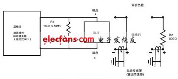
1) ESD sensitivity test in human body model
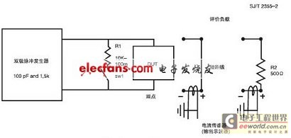
Figure 1 Schematic diagram of ESD sensitivity test in human body model
① The bipolar pulse generator should be designed to avoid repeated charging and double pulse generation. Bipolar performance cannot be obtained by swapping the A and B terminals.
② Switch SW1 must be closed for 10ms to 100ms after the pulse passes to ensure that the tested socket is not in a charging state. It should also be opened at least 10ms before the next pulse arrives. Resistor R1 is connected in series with the switch to ensure a slow discharge of the device, thus avoiding the possibility of a charged device mode discharge.
③ In Figure 1, the evaluation resistor load 1 is: a tinned copper short-circuit with a cross-section of 0.83mm2 to 0.21mm2, and a span suitable for the test socket. Load 2 is: 500Ω, ±1%, 1000V, low inductance film resistor.
④ Oscilloscope requirements: minimum sensitivity 100mA/cm (current sensor), bandwidth 350MHz, minimum writing rate 1cm/ns.
⑤ Current sensor requirements
Minimum bandwidth 350MHz;
Peak pulse current 12A;
Rise time is less than 1ns;
Can use solid conductors with a diameter of 1.5 mm;
Can provide output voltage of 1mv/mA~5mv/mA;
⑥ The situation where a socket is stacked on the test socket (the second socket is stacked on the main test socket) is allowed only if the waveform of the second socket meets the requirements of this standard;
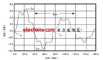
⑦ Use the short-circuit line to obtain the current waveforms of each sensitivity level, and modify these waveforms to meet the requirements of Figure 2;
⑧ The current pulse should meet the following characteristics
Pulse rise time tr: 5ns~25ns;
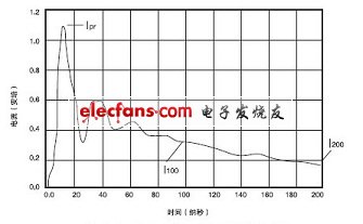
The maximum allowable ringing wave peak-to-peak value Ir must be less than 15% of Ipr, and there must be no obvious ringing wave within 100ns after the pulse starts;
As shown in Figure 4, Ipr is the peak current through the 500Ω load resistor, and it should be between 375mA and 500mA for a 1000V pre-charge voltage. For a 4000V pre-charge voltage, it should be between 1.5A and 2.2A. It should not be less than 63% of the Ips value measured earlier for the same sensitivity level.
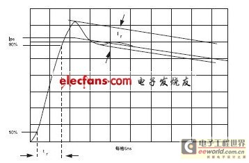
Figure 2 Current pulse through a short circuit

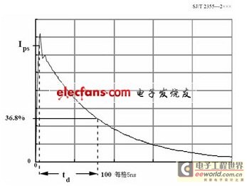
Figure 3 Current waveform through the short circuit

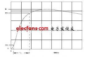
Figure 4 Current waveform through a 500Ω resistor




Previous article:LED backlight/lighting driver IC series introduction
Next article:Implementation of a wireless LED information publishing system
Recommended ReadingLatest update time:2024-11-17 01:37


- Popular Resources
- Popular amplifiers
- MathWorks and NXP Collaborate to Launch Model-Based Design Toolbox for Battery Management Systems
- STMicroelectronics' advanced galvanically isolated gate driver STGAP3S provides flexible protection for IGBTs and SiC MOSFETs
- New diaphragm-free solid-state lithium battery technology is launched: the distance between the positive and negative electrodes is less than 0.000001 meters
- [“Source” Observe the Autumn Series] Application and testing of the next generation of semiconductor gallium oxide device photodetectors
- 采用自主设计封装,绝缘电阻显著提高!ROHM开发出更高电压xEV系统的SiC肖特基势垒二极管
- Will GaN replace SiC? PI's disruptive 1700V InnoMux2 is here to demonstrate
- From Isolation to the Third and a Half Generation: Understanding Naxinwei's Gate Driver IC in One Article
- The appeal of 48 V technology: importance, benefits and key factors in system-level applications
- Important breakthrough in recycling of used lithium-ion batteries
- Innolux's intelligent steer-by-wire solution makes cars smarter and safer
- 8051 MCU - Parity Check
- How to efficiently balance the sensitivity of tactile sensing interfaces
- What should I do if the servo motor shakes? What causes the servo motor to shake quickly?
- 【Brushless Motor】Analysis of three-phase BLDC motor and sharing of two popular development boards
- Midea Industrial Technology's subsidiaries Clou Electronics and Hekang New Energy jointly appeared at the Munich Battery Energy Storage Exhibition and Solar Energy Exhibition
- Guoxin Sichen | Application of ferroelectric memory PB85RS2MC in power battery management, with a capacity of 2M
- Analysis of common faults of frequency converter
- In a head-on competition with Qualcomm, what kind of cockpit products has Intel come up with?
- Dalian Rongke's all-vanadium liquid flow battery energy storage equipment industrialization project has entered the sprint stage before production
- Allegro MicroSystems Introduces Advanced Magnetic and Inductive Position Sensing Solutions at Electronica 2024
- Car key in the left hand, liveness detection radar in the right hand, UWB is imperative for cars!
- After a decade of rapid development, domestic CIS has entered the market
- Aegis Dagger Battery + Thor EM-i Super Hybrid, Geely New Energy has thrown out two "king bombs"
- A brief discussion on functional safety - fault, error, and failure
- In the smart car 2.0 cycle, these core industry chains are facing major opportunities!
- Rambus Launches Industry's First HBM 4 Controller IP: What Are the Technical Details Behind It?
- The United States and Japan are developing new batteries. CATL faces challenges? How should China's new energy battery industry respond?
- Murata launches high-precision 6-axis inertial sensor for automobiles
- Ford patents pre-charge alarm to help save costs and respond to emergencies
- BLE Bluetooth Protocol - BLE connection establishment process summary
- Today at 10:00 AM, live broadcast with prizes: [Introduction to TI's GaN-based applications]
- AD20.0.13 gets stuck when starting Adding View: Explorer under WIN10.
- IIC bus MSP430F149 and 24c16 comprehensive experiment programming example
- Why are the high-precision positioning systems of Beidou and GPS not open to ordinary users?
- Low power solar cell charging
- Why are the wild elephants heading north? Use your imagination and make bold predictions!
- Bose small speaker disassembly
- Guangdong Tonly Semiconductor suffered a confined space suffocation accident: 4 workers from the outsourcing unit died
- LIS3MDL evaluation board STEVAL-MKI137V1 data

 Siemens PLC Project Tutorial
 LED Cube Code
 ESP32-S3 source code


 京公网安备 11010802033920号