Digital management of high-availability power supplies holds great promise, but this digital management often comes at the cost of complex multi-chip circuit solutions. For example, an application with voltage/current monitoring and power margin control capabilities may require many integrated circuits, such as a low-drift reference, a multi-channel differential input ADC with at least 12-bit resolution, an 8-bit DAC, and a dedicated microcontroller. Additionally, implementing the margin control algorithm, voltage and current monitor functionality requires considerable software development effort. Add cost, complexity, larger board area requirements and longer design debugging times, and even the most expert power supply designers may be afraid to attempt to manage power digitally.
The LTC2970 is a dual channel power supply monitor and controller. This device simplifies the design of digital power management by incorporating several important functions into a single, easy-to-use chip. The LTC2970 highlights the following features:
● 14-bit, differential input, ΔΣ ADC with ±0.5% maximum total unadjusted error (TUE) over the entire industrial temperature range using an on-chip reference.
●7-channel ADC multiplexer with 4 external differential inputs, a 12V input, a 5VVDD input and an input for the on-chip temperature sensor.
●Two continuous-time, 8-bit current output DACs with voltage buffer outputs that can be set to low-leakage, high-impedance states.
●Built-in closed-loop servo algorithm to adjust the load point voltage of the DC/DC converter to the desired value. Two external resistors allow the user to adjust the range and resolution of the voltage servo loop.
●Extensive, user-configurable overvoltage and undervoltage fault monitoring methods.
●An I 2 C and SMBus compatible two-wire serial bus interface, two GPIO pins and an ALERT pin.
●An on-chip 5V linear regulator allows the LTC2970 to operate from an external power supply of 8V to 15V.
● Another device in this series, the LTC2970-1, adds a tracking algorithm that allows two or more power supplies to ramp up or down in a controlled manner.
Margining and Monitoring Applications
Figure 1 shows a typical application circuit for monitoring and margining a DC/DC converter using external feedback resistors.

While input V IN0_B monitors the voltage on sense resistor R50, the V IN0_A differential input of the LTC2970 directly senses the voltage at the point of load. By comparing the digitized point-of-load voltage to the target voltage using a linear search algorithm, the DC/DC converter's output voltage margin can be precisely controlled to a value programmed by the user. The current provided by ID AC0 can then be adjusted as desired by 1 LSB per servo iteration. This current induces a correction voltage across resistor R40, referenced to point-of-load ground, which is buffered to the V OUT0 pin. The voltage difference generated between the V OUT0 pin and the converter feedback node is multiplied by the coefficient R20/R30 and added to the nominal output voltage of the DC/DC converter, thus closing the servo loop. When voltage margin control is disabled, the converter's feedback node can be isolated from the LTC2970 by setting the V OUT0 pin to a high-impedance state.
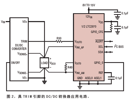
Figure 2 shows the LTC2970 applied to a DC/DC converter with TRIM pins. As shown in Figure 1, two external resistors are required: V OUT0 is connected to the TRIM pin through resistor R30, while I OUT0 is terminated by R40 to the load point ground of the DC/DC converter. Upon power-up, the V OUT0 pin enters its default high-impedance state, allowing the DC/DC converter to power up to its nominal output voltage. After power-up, the LTC2970's soft-connect feature can be used to automatically find the IDAC code closest to the TRIM pin open circuit voltage before turning on V OUT0 .

In applications that require sequencing, the LTC2970 can be configured to delay the start-up of the DC/DC converter on power-up by asserting the GPIO_CFG pin high. This causes the GPIO_0 pin to automatically pull the DC/DC converter's RUN pin low, which remains low until the SMBus-compatible I2C interface releases the RUN pin.
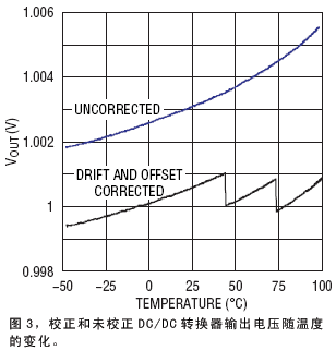
The absolute accuracy of the LTC2970 is shown in Figure 3. The LTC2970 is configured so that if the voltage of the LTC3728 DC/DC converter deviates by more than ±1%, the LTC2970 follows one of the converter's outputs up to 1V. The LTC2970 can very easily maintain the output voltage within ±1mV of 1V when heated together from -50°C to 100°C with the DC/DC converter. When the LTC2970 is isolated from the LTC3728, the LTC2970's output voltage drifts between 1.002V and 1.0055V over the same temperature range.

Features
The LTC2970 has several beneficial features that set it apart from similar solutions.
Delta-Sum ADC
The LTC2970's ADC is a second-order delta-sigma (ΔΣ) modulator followed by a sinc 2 digital filter that converts the modulator's serial data into a 14-bit word at a 30Hz conversion rate. The ADC's TUE is less than ±0.5% when using an on-chip reference.
An advantage of the ΔΣ ADC compared to traditional ADCs is the on-chip digital filtering, which, coupled with the large oversampling rate (OSR = 512), makes the LTC2970 insensitive to noise effects when sampling the supply voltage. The LTC2970's sinc 2 digital filter provides high rejection at all frequencies except integer multiples of the modulator sampling frequency (fs = 30.72kHz) . Adding a simple RC low-pass filter to the input of the ADC can attenuate ripple components that may cause DC aliasing.
The ADC's differential input monitors the supply voltage at the point of load and senses the resistor voltage. The differential mode and common mode input range is -0.3V~6V. The ADC has a resolution of 500mV/LSB and can resolve voltages when the sense resistor resistance is only a few milliohms and the load current on the sense resistor varies over a wide range. For switching power supply applications without a sense resistor, the load current can be measured through the DC resistance of the inductor using the application circuit shown in Figure 4.
Previous article:Designing a digital programmable current source using DAC
Next article:Design and performance test of a high-efficiency flyback switching power supply
Recommended ReadingLatest update time:2024-11-16 19:37


- Popular Resources
- Popular amplifiers
-
 Microgrid Stability Analysis and Control Microgrid Modeling Stability Analysis and Control to Improve Power Distribution and Power Flow Control (
 -
 Modern Electronic Technology Training Course (Edited by Yao Youfeng)
 -
 New Energy Vehicle Control System Inspection and Maintenance (Edited by Bao Pili)
 -
 Intelligent Control Technology of Permanent Magnet Synchronous Motor (Written by Wang Jun)
- MathWorks and NXP Collaborate to Launch Model-Based Design Toolbox for Battery Management Systems
- STMicroelectronics' advanced galvanically isolated gate driver STGAP3S provides flexible protection for IGBTs and SiC MOSFETs
- New diaphragm-free solid-state lithium battery technology is launched: the distance between the positive and negative electrodes is less than 0.000001 meters
- [“Source” Observe the Autumn Series] Application and testing of the next generation of semiconductor gallium oxide device photodetectors
- 采用自主设计封装,绝缘电阻显著提高!ROHM开发出更高电压xEV系统的SiC肖特基势垒二极管
- Will GaN replace SiC? PI's disruptive 1700V InnoMux2 is here to demonstrate
- From Isolation to the Third and a Half Generation: Understanding Naxinwei's Gate Driver IC in One Article
- The appeal of 48 V technology: importance, benefits and key factors in system-level applications
- Important breakthrough in recycling of used lithium-ion batteries
- Innolux's intelligent steer-by-wire solution makes cars smarter and safer
- 8051 MCU - Parity Check
- How to efficiently balance the sensitivity of tactile sensing interfaces
- What should I do if the servo motor shakes? What causes the servo motor to shake quickly?
- 【Brushless Motor】Analysis of three-phase BLDC motor and sharing of two popular development boards
- Midea Industrial Technology's subsidiaries Clou Electronics and Hekang New Energy jointly appeared at the Munich Battery Energy Storage Exhibition and Solar Energy Exhibition
- Guoxin Sichen | Application of ferroelectric memory PB85RS2MC in power battery management, with a capacity of 2M
- Analysis of common faults of frequency converter
- In a head-on competition with Qualcomm, what kind of cockpit products has Intel come up with?
- Dalian Rongke's all-vanadium liquid flow battery energy storage equipment industrialization project has entered the sprint stage before production
- Allegro MicroSystems Introduces Advanced Magnetic and Inductive Position Sensing Solutions at Electronica 2024
- Car key in the left hand, liveness detection radar in the right hand, UWB is imperative for cars!
- After a decade of rapid development, domestic CIS has entered the market
- Aegis Dagger Battery + Thor EM-i Super Hybrid, Geely New Energy has thrown out two "king bombs"
- A brief discussion on functional safety - fault, error, and failure
- In the smart car 2.0 cycle, these core industry chains are facing major opportunities!
- The United States and Japan are developing new batteries. CATL faces challenges? How should China's new energy battery industry respond?
- Murata launches high-precision 6-axis inertial sensor for automobiles
- Ford patents pre-charge alarm to help save costs and respond to emergencies
- New real-time microcontroller system from Texas Instruments enables smarter processing in automotive and industrial applications
- [Xingkong Board Python Programming Learning Main Control Board] Python development environment experience - graphic code can be quickly started
- Method of measuring automobile throttle sensor signal with auto repair oscilloscope
- How to detect whether the switching power supply transformer is good or bad?
- How to enable TI 15.4-Stack to support 470M frequency band
- 【Development Kit for nRF52840】+ Review 5-thread trial
- How to determine whether the EN enable pin of the chip needs a series resistor?
- Looking for a constant current chip
- [National Technology N32G457 Review] RT_Thread Studio transplants USB virtual serial port
- Xunwei 4418 development board Linux system TFTP transfer file
- Thermal Design of Semiconductor Components: Heat Transfer and Heat Dissipation Paths

 Microgrid Stability Analysis and Control Microgrid Modeling Stability Analysis and Control to Improve Power Distribution and Power Flow Control (


 京公网安备 11010802033920号