There are many kinds of flow meters according to their working principles. When selecting a flow meter, you need to choose the appropriate flow meter according to the actual working conditions. Below, the editor summarizes the working principles of common flow meters such as differential pressure flow meters, target flow meters, volumetric flow meters, turbine flow meters, etc., hoping to be helpful to everyone.
1. Differential pressure flow meter
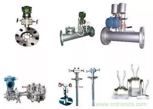
The differential pressure flowmeter is an instrument that calculates the flow rate based on the differential pressure generated by the flow detection component installed in the pipeline, the known fluid conditions and the geometric dimensions of the detection component and the pipeline. The differential pressure flowmeter consists of a primary device (detection component) and a secondary device (differential pressure conversion and flow display instrument). Differential pressure flowmeters are usually classified in the form of detection components, such as orifice flowmeters, venturi flowmeters, and average velocity tube flowmeters. The secondary device is a variety of mechanical, electronic, and electromechanical integrated differential pressure gauges, differential pressure transmitters, and flow display instruments. It has developed into a large category of instruments with a high degree of three-dimensionalization (serialization, generalization, and standardization) and a large variety of specifications. It can measure both flow parameters and other parameters (such as pressure, level, density, etc.).
The detection parts of differential pressure flowmeters can be divided into several categories according to their working principles: throttling device, hydraulic resistance type, centrifugal type, dynamic pressure head type, dynamic pressure head gain type and jet type.
Differential pressure flowmeter is the most widely used type of flowmeter, and its usage ranks first among all types of flowmeters. In recent years, due to the advent of various new flowmeters, its usage percentage has gradually decreased, but it is still the most important type of flowmeter.
2. Target flow meter
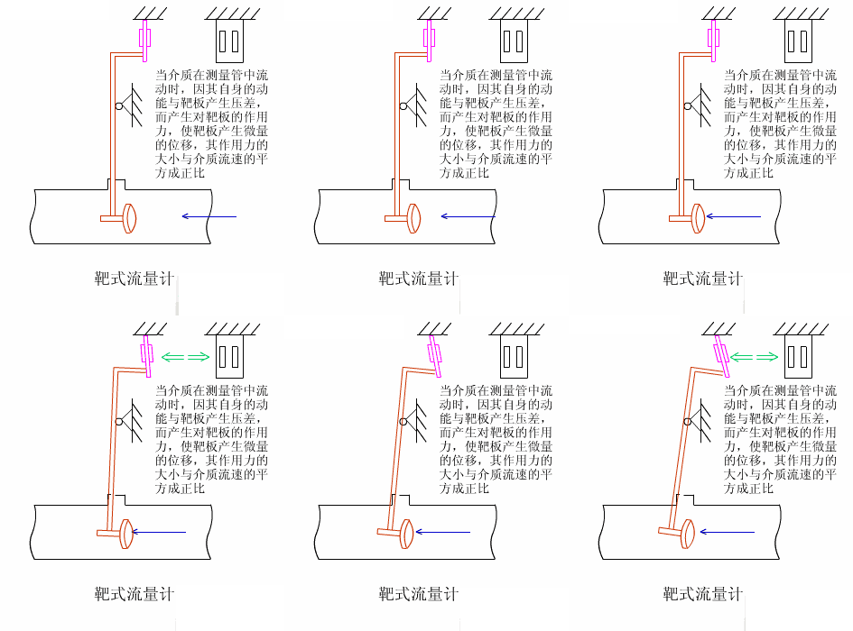
Target flowmeters have been used in industrial flow measurement since the 1960s, mainly for solving the flow measurement of high viscosity and low Reynolds number fluids. They have gone through two major development stages: pneumatic meters and electric meters. The SBL series intelligent target flowmeter is a new type of flow meter developed based on the measurement principle of the original strain gauge (capacitive) target flowmeter, using the latest force sensing sensor as the measurement and sensitive transmission element, and utilizing modern digital intelligent processing technology.
3. Positive displacement flow meter
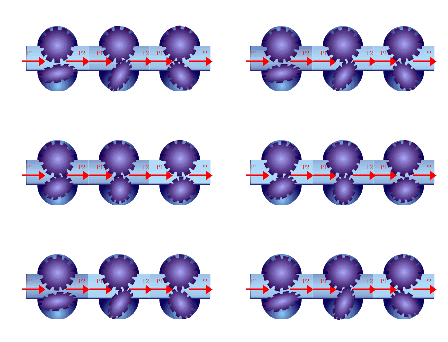
Positive displacement flowmeter, also known as fixed displacement flowmeter, PD flowmeter for short, is the most accurate type of flow meter. It uses mechanical measuring elements to continuously divide the fluid into a single known volume portion, and measures the total volume of the fluid according to the number of times the measuring chamber is repeatedly filled and discharged with the volume portion of fluid.
Positive displacement flow meters can be classified according to their measuring elements into oval gear flow meters, scraper flow meters, double rotor flow meters, rotary piston flow meters, reciprocating piston flow meters, disc flow meters, liquid-sealed drum flow meters, wet gas meters and membrane gas meters.
4. Turbine flow meter
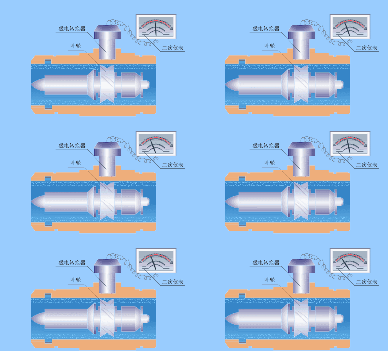
Turbine flowmeter is the main type of velocity flowmeter. It uses a multi-blade rotor (turbine) to sense the average flow velocity of the fluid and derive the flow rate or total amount. Generally, it consists of two parts: a sensor and a display, and can also be made into an integral type.
Turbine flowmeter, volumetric flowmeter and mass flowmeter are called three types of flowmeters with high repeatability and precision, and are one of the ten major types of flowmeters.
5. Electromagnetic flow meter
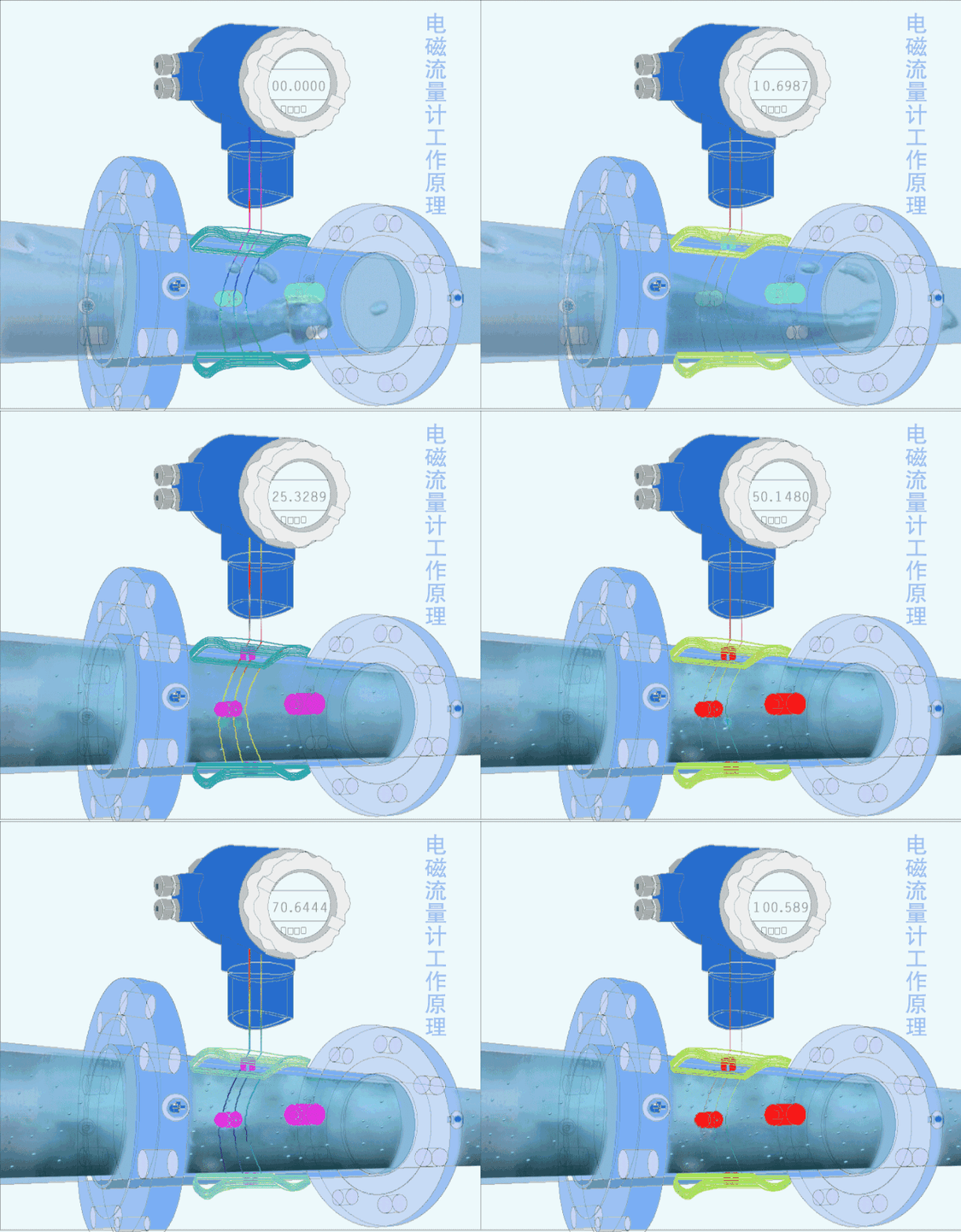
The electromagnetic flowmeter is an instrument for measuring conductive liquids based on Faraday's law of electromagnetic induction.
Electromagnetic flowmeters have a series of excellent characteristics that can solve problems that other flowmeters are difficult to apply, such as the measurement of dirty flow and corrosive flow.
6. Vortex flowmeter
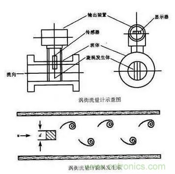
Vortex flowmeter is a meter that places a non-streamlined vortex generator in the fluid, and the fluid is alternately separated on both sides of the generator to release two strings of regularly staggered vortices. Vortex flowmeters can be divided into stress type, strain type, capacitance type, thermal type, vibration type, photoelectric type and ultrasonic type according to the frequency detection method.
7. Ultrasonic flow meter
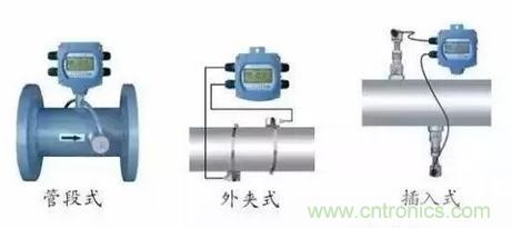
Ultrasonic flowmeter is an instrument that measures flow by detecting the effect of fluid flow on ultrasonic beam (or ultrasonic pulse). According to the principle of signal detection, ultrasonic flowmeter can be divided into propagation velocity difference method (direct time difference method, time difference method, phase difference method and frequency difference method), beam deviation method, Doppler method, cross-correlation method, spatial filter method and noise method.
Like electromagnetic flowmeters, ultrasonic flowmeters are non-obstructive flowmeters because there are no obstructions in the flow channel of the instrument. They are a type of flowmeter suitable for solving difficult flow measurement problems, especially in large-diameter flow measurement.
8. Coriolis mass flow meter
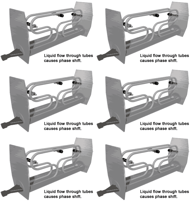
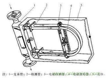
Coriolis mass flowmeter is a novel instrument that directly and accurately measures the mass flow of fluids. The main structure adopts two U-shaped tubes side by side. The curved parts of the two tubes are slightly vibrated towards each other, and the straight tubes on both sides will vibrate accordingly, that is, they will move together or open at the same time, that is, the vibration of the two tubes is synchronous and symmetrical. If the fluid is introduced into the tube while the tube is vibrating synchronously and flows forward along the tube, the tube will force the fluid to vibrate up and down with it.
9. Thermal mass flow meter
The thermal flow meter sensor contains two sensing elements, a velocity sensor and a temperature sensor. They automatically compensate and correct for changes in gas temperature. The electric heating part of the meter heats the velocity sensor to a certain value higher than the operating temperature, so that a constant temperature difference is formed between the velocity sensor and the sensor measuring the operating temperature. When the temperature difference is kept constant, the energy consumed by the electric heating, or the heat dissipation value, is proportional to the mass flow rate of the gas flowing through.
10.Metal rotor flowmeter
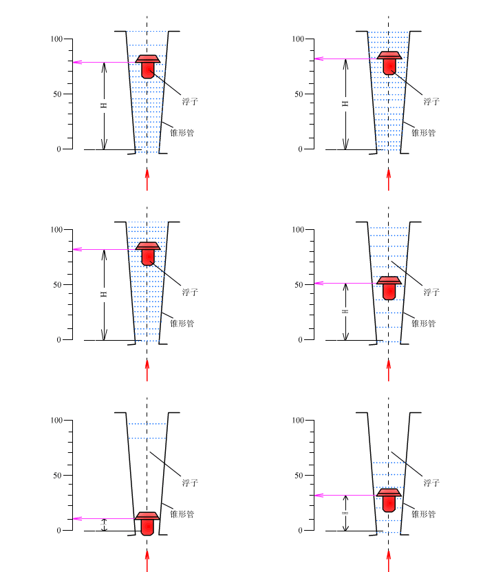
The rotor flowmeter consists of two parts. One is a tapered tube that gradually expands from bottom to top; the other is a rotor placed in the tapered tube and can move freely up and down along the center line of the tube. When the rotor flowmeter measures the flow of a fluid, the measured fluid flows in from the lower end of the tapered tube, and the flow of the fluid impacts the rotor and generates a force on it (the magnitude of this force varies with the flow); when the flow is large enough, the force generated will lift the rotor and raise it. At the same time, the measured fluid flows through the annular section between the rotor and the tapered tube wall. At this time, there are three forces acting on the rotor: the dynamic pressure of the fluid on the rotor, the buoyancy of the rotor in the fluid, and the weight of the rotor itself.
When the flowmeter is installed vertically, the center of gravity of the rotor will coincide with the axis of the cone tube, and the three forces acting on the rotor are all in the direction parallel to the axis of the tube. When these three forces are balanced, the rotor will float steadily at a certain position in the cone tube. For a given rotor flowmeter, the size and shape of the rotor have been determined, so its buoyancy and its own gravity in the fluid are known constants. Only the dynamic pressure of the fluid on the float changes with the flow rate of the incoming flow. Therefore, when the incoming flow rate increases or decreases, the rotor will move up or down, and the flow cross-sectional area at the corresponding position will also change until the flow rate becomes the corresponding speed when balanced, and the rotor will stabilize at the new position. For a given rotor flowmeter, the position of the rotor in the cone tube is in a one-to-one correspondence with the flow rate of the fluid flowing through the cone tube.
11. Orifice flow meter
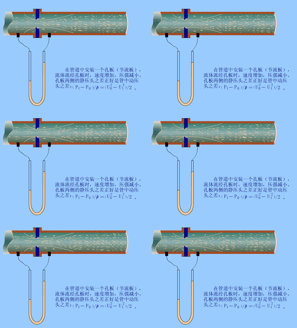
The fluid that fills the pipeline flows through the throttling device in the pipeline, causing local contraction near the throttling device, increasing the flow rate, and generating a static pressure difference on the upstream and downstream sides. Under the condition that the relevant parameters are known, the relationship between the differential pressure and the flow rate can be derived based on the flow continuity principle and the Bernoulli equation to obtain the flow rate.
12. Open channel flow meter
Different from the above mentioned types, it is a flow meter that measures the free surface natural flow in a non-full tubular open channel.
The working principle of the open channel flowmeter is to use open channel technology to measure the fluid level height, and then calculate the flow rate through the microprocessor inside the instrument. Because it is a non-contact measurement, the open channel flowmeter can be used in harsh environments. Under the control of a microcomputer, the open channel flowmeter transmits and receives the open channel, and calculates the distance between the open channel flowmeter and the measured liquid surface based on the transmission time, thereby obtaining the liquid level height. Since there is a certain proportional relationship between the liquid level and the flow rate, the liquid flow rate Q can be finally obtained according to the calculation formula.
Previous article:Overcoming the epidemic, the first fully automated SiC dynamic test system in the Greater Bay Area was delivered to the Beijing Institute of Technology Automotive Research Institute
Next article:How to achieve accurate and reliable low temperature measurement?
- Keysight Technologies Helps Samsung Electronics Successfully Validate FiRa® 2.0 Safe Distance Measurement Test Case
- From probes to power supplies, Tektronix is leading the way in comprehensive innovation in power electronics testing
- Seizing the Opportunities in the Chinese Application Market: NI's Challenges and Answers
- Tektronix Launches Breakthrough Power Measurement Tools to Accelerate Innovation as Global Electrification Accelerates
- Not all oscilloscopes are created equal: Why ADCs and low noise floor matter
- Enable TekHSI high-speed interface function to accelerate the remote transmission of waveform data
- How to measure the quality of soft start thyristor
- How to use a multimeter to judge whether a soft starter is good or bad
- What are the advantages and disadvantages of non-contact temperature sensors?
- Innolux's intelligent steer-by-wire solution makes cars smarter and safer
- 8051 MCU - Parity Check
- How to efficiently balance the sensitivity of tactile sensing interfaces
- What should I do if the servo motor shakes? What causes the servo motor to shake quickly?
- 【Brushless Motor】Analysis of three-phase BLDC motor and sharing of two popular development boards
- Midea Industrial Technology's subsidiaries Clou Electronics and Hekang New Energy jointly appeared at the Munich Battery Energy Storage Exhibition and Solar Energy Exhibition
- Guoxin Sichen | Application of ferroelectric memory PB85RS2MC in power battery management, with a capacity of 2M
- Analysis of common faults of frequency converter
- In a head-on competition with Qualcomm, what kind of cockpit products has Intel come up with?
- Dalian Rongke's all-vanadium liquid flow battery energy storage equipment industrialization project has entered the sprint stage before production
- New breakthrough! Ultra-fast memory accelerates Intel Xeon 6-core processors
- New breakthrough! Ultra-fast memory accelerates Intel Xeon 6-core processors
- Consolidating vRAN sites onto a single server helps operators reduce total cost of ownership
- Consolidating vRAN sites onto a single server helps operators reduce total cost of ownership
- Allegro MicroSystems Introduces Advanced Magnetic and Inductive Position Sensing Solutions at Electronica 2024
- Car key in the left hand, liveness detection radar in the right hand, UWB is imperative for cars!
- After a decade of rapid development, domestic CIS has entered the market
- Aegis Dagger Battery + Thor EM-i Super Hybrid, Geely New Energy has thrown out two "king bombs"
- A brief discussion on functional safety - fault, error, and failure
- In the smart car 2.0 cycle, these core industry chains are facing major opportunities!
- Feedback circuits in electronic circuits
- TI - Delivering Ultra-High Power Density for 100W USB Power Delivery Adapters
- Seeking routines for driving LPS33HW pressure sensor of STM32F103 series
- The software engineer said he doesn't know how to use GPIO to simulate I2C. Is he a newbie?
- L3 value range
- EEWORLD University Hall----Live playback: TI Zigbee 3.0 and multi-protocol solutions
- Beckham resigns as captain
- LSM6DS3TR-C related information
- Solutions to counteract noise issues in Wi-Fi-equipped devices
- LED Timer Keychain


 MAX35101 pdf English version
 AB PLC例程 [MMS_044766]Configurable Flow Meter Module in Generic profile
 Design of Interface Circuit Between ADS1110 and AT89C51 Single Chip Microcomputer System


 京公网安备 11010802033920号