The quality of switching power supplies directly affects the performance, safety and reliability of the product. Many power supply test items, large amount of calculation, cumbersome statistics and other issues have always troubled engineers. This article will explain several important test items for switching power supplies.
Oscilloscope power supply test analysis mainly uses an oscilloscope to perform relevant tests on power supplies (switching power supplies), improve the work efficiency of power supply developers, and facilitate the testing of power supply modules. It mainly involves tests related to switching power supplies (AC/DC).
The popular DC power supply structure in most modern systems is the switching power supply (SMPS), which is well known for its ability to handle load changes efficiently. The power signal path of a typical SMPS includes passive components, active components, and magnetic components. SMPS minimizes the use of lossy components such as resistors and linear mode transistors, and focuses on (under ideal conditions) lossless components such as switching transistors, capacitors, and magnetic components. Its main components are shown in Figure 1.
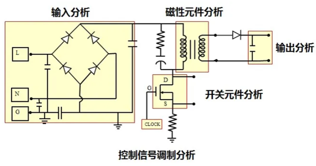
Figure 1 Schematic diagram of switching power supply
The test parameters of the switching power supply mainly include input end analysis, output end analysis, magnetic component analysis, switching device analysis, modulation analysis, loop analysis, etc. As shown in Figure 2 below, after the oscilloscope enters the power supply analysis test interface, the test items corresponding to each test function.
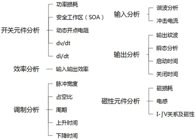
Figure 2 Power supply analysis project
Input Analysis - Harmonic Test
Since the generation of power supply harmonics will increase the harmonic loss of the power supply system, reduce the power supply utilization rate, cause the power supply end load and other equipment to overload, shorten the service life, and may also cause resonance, causing various devices to be damaged due to excessive current or voltage, etc., so the parameter testing and analysis of harmonics is very important.
Oscilloscopes above the ZDS3000 series can test the 0-40th current harmonic limited value according to IEC61000-3-2. According to the limit on harmonic current, the equipment can be divided into four categories: ABCD, and support the export report of harmonic effective value. The oscilloscope harmonic test interface is shown in Figure 3 below.
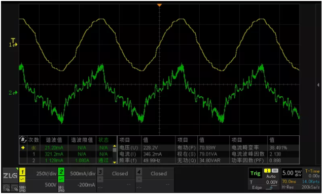
Figure 3 Current harmonic test interface
Order: The harmonic order ranges from 0 to 40.
Harmonic value: used to display the effective value of a certain current harmonic component, using a unified unit that is dynamically determined by the maximum value.
Harmonic limit: Harmonic limit is dynamically calculated based on the A, B, C, and D standards of IEC 61000-3-2. Different current limits will be obtained when different categories are selected.
Status: This status is used to show the result after comparison with the standard.
Output analysis - output ripple
Output ripple mainly refers to the AC component in the output DC. Ripple may be generated in the circuit frequency and the switching frequency. Some devices are very sensitive to these ripples, so the ripple of the power supply output must be measured. The ripple size is generally mV, expressed in peak-to-peak value.
The oscilloscope power analysis function provides a quick test of the output ripple selection. Select the output ripple through Analyze, set the configuration, and you can quickly get the output ripple parameters. It also supports exporting reports.
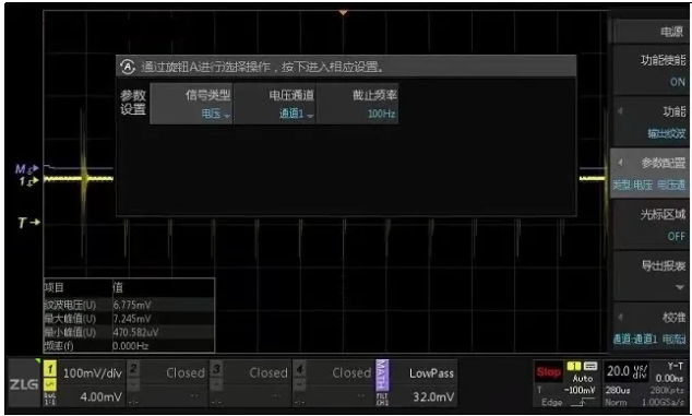
Figure 4 Output ripple test interface
Switching Component Analysis - Switching Loss Test
The switching device of the switching power supply always works in the on or off state, which can provide higher efficiency. Ideally, there is no loss when the switching device is turned on and off, but in reality, there is power loss when the switching device is working. It mainly includes switching loss and conduction loss. As shown in Figure 5 below.
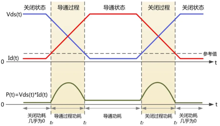
Figure 5 Actual switching loss
The main calculation for power loss mainly includes the sum of three parts:
Turn-on process loss + turn-off process loss + conduction loss
Ploss = Pon + Poff + Pcond
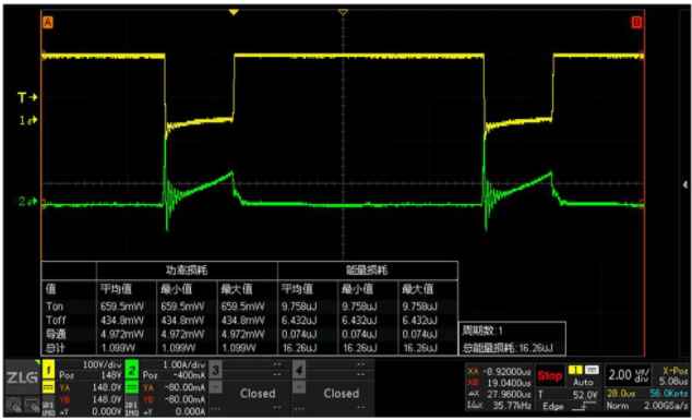
Figure 6 Switching loss test interface
Value: The result in this row is the calculation result of the current sample; it can be used as a reference value for the final result.
Maximum, minimum and average: statistical results. You can use Clear to clear and restart the statistics.
Maximum power statistics (P): maximum instantaneous power value.
Maximum energy statistic (E): The energy corresponding to the instantaneous power, and its time is one sampling interval.
Power average statistic (P): the average power of the entire sample.
In addition to the switching loss test, there are also SOA (safe operating area) that can be used for incoming material inspection or verification of the performance utilization of switching devices, dynamic open-point resistance, dv/dt, di/dt and other analysis functions, which will be introduced in detail in subsequent articles.
Modulation module analysis
Modulation analysis is used to measure power supply control loops. Modulation analysis is often used to characterize the feedback from the DC output to the pulse width modulation (PWM) of the gate terminal of the switching transistor to achieve dynamic voltage regulation.
For modulation analysis, the following test points are mainly involved: pulse analysis, duty cycle, period, frequency, rise time and fall time.
Since a detailed introduction would take up a lot of space, I will explain it to you in detail later.
Magnetic analysis
Passive components are those that do not amplify signals or switch them. Power supplies use a full range of passive components, such as resistors and capacitors, but from a measurement perspective, the main focus is on magnetic components (magnetic devices), especially inductors and transformers. Both inductors and transformers consist of an iron core with several turns of copper wire wrapped around it.
An inductor's impedance increases with frequency, blocking higher frequencies more than lower frequencies, making it suitable for filtering current on power supply inputs and outputs.
Some of the metrics that help determine power supply performance include:
● Inductor
● Power loss (magnetic components)
● I-∫V relationship and magnetic properties
In order to calculate these data, it is necessary to set the parameters of the magnetic components. First, you must determine the unit to be used, SI or CGS. Depending on the unit, the configuration and range of the parameters are slightly different. The parameters that need to be configured are:
S -- coil cross section
L -- average magnetic path length
V -- Core volume
Power supplies use inductors as energy storage devices, filters, or transformers. As transformers, inductors can help maintain oscillations in switch-mode power supplies. Designers need to monitor the behavior of such devices under operating conditions. The inductance value depends on the current and voltage sources, the excitation signal, the waveform, and the operating frequency.
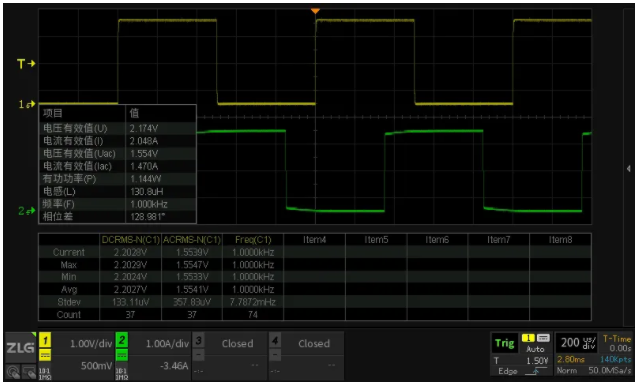
Figure 7 Magnetic analysis test interface
Previous article:Reasons and analysis of the failure of triggering the automatic function of the oscilloscope to measure low-frequency signals
Next article:Ensure SiC validation test accuracy and effectively measure signals in SiC power electronics systems
- Popular Resources
- Popular amplifiers
-
 Multisim Circuit System Design and Simulation Tutorial
 -
 A_2.89_uW_Dry-Electrode_Enabled_Clockless_Wireless_ECG_SoC_for_Wearable_Applications
 -
 Design of a low voltage low dropout regulator with auxiliary push-pull output stage circuit
 -
 Measuring 2nV/√Hz Noise and 120dB Power Supply Rejection on a Linear Regulator
- New IsoVu™ Isolated Current Probes: Bringing a New Dimension to Current Measurements
- Modern manufacturing strategies drive continuous improvement in ICT online testing
- Methods for Correlation of Contact and Non-Contact Measurements
- Keysight Technologies Helps Samsung Electronics Successfully Validate FiRa® 2.0 Safe Distance Measurement Test Case
- From probes to power supplies, Tektronix is leading the way in comprehensive innovation in power electronics testing
- Seizing the Opportunities in the Chinese Application Market: NI's Challenges and Answers
- Tektronix Launches Breakthrough Power Measurement Tools to Accelerate Innovation as Global Electrification Accelerates
- Not all oscilloscopes are created equal: Why ADCs and low noise floor matter
- Enable TekHSI high-speed interface function to accelerate the remote transmission of waveform data
- Intel promotes AI with multi-dimensional efforts in technology, application, and ecology
- ChinaJoy Qualcomm Snapdragon Theme Pavilion takes you to experience the new changes in digital entertainment in the 5G era
- Infineon's latest generation IGBT technology platform enables precise control of speed and position
- Two test methods for LED lighting life
- Don't Let Lightning Induced Surges Scare You
- Application of brushless motor controller ML4425/4426
- Easy identification of LED power supply quality
- World's first integrated photovoltaic solar system completed in Israel
- Sliding window mean filter for avr microcontroller AD conversion
- What does call mean in the detailed explanation of ABB robot programming instructions?
- USB Type-C® and USB Power Delivery: Designed for extended power range and battery-powered systems
- RAQ #223: How to measure and determine soft-start timing without a soft-start equation?
- RAQ #223: How to measure and determine soft-start timing without a soft-start equation?
- GigaDevice's full range of automotive-grade SPI NOR Flash GD25/55 wins ISO 26262 ASIL D functional safety certification
- GigaDevice's full range of automotive-grade SPI NOR Flash GD25/55 wins ISO 26262 ASIL D functional safety certification
- New IsoVu™ Isolated Current Probes: Bringing a New Dimension to Current Measurements
- New IsoVu™ Isolated Current Probes: Bringing a New Dimension to Current Measurements
- Infineon Technologies Launches ModusToolbox™ Motor Kit to Simplify Motor Control Development
- Infineon Technologies Launches ModusToolbox™ Motor Kit to Simplify Motor Control Development
- STMicroelectronics IO-Link Actuator Board Brings Turnkey Reference Design to Industrial Monitoring and Equipment Manufacturers
- Tesla Robot Optimus Prime Conference Uncut 4K HD Episode 2
- FPGA error, added clock timing, and how to solve this error
- [Project source code] FPGA-based Gigabit Ethernet module UDP design example program
- Here it comes! Summary of 2021 National College Entrance Examination Essay Questions
- LE Audio audio sharing will stimulate a new wave of audio innovation
- Understanding IGBT Drivers in One Article
- A question of the direction of energy transmission
- How to calibrate the clock of MSP430F2131
- Interview experience of Texas Instruments Reliability Engineer in Fall 2018
- What factors are related to the communication distance? Why is the module communication distance different from what the manufacturer advertises?

 Multisim Circuit System Design and Simulation Tutorial


 京公网安备 11010802033920号