As 5G and IoT connected devices and related high bandwidth requirements are expected to increase significantly, data center operators need to migrate to higher bandwidth networks, where bandwidth must exceed the current commonly used 100 GB Ethernet (100GE). Migrating to next-generation 400GE networks requires faster memory and higher-speed serial bus communications. In addition to upgrading Ethernet interfaces to 400GE, servers also need to adopt higher-speed serial expansion bus interfaces and memory.
The PCIe (PCI Express) expansion bus is now migrating to the newly standardized PCIe 5.0, also known as PCIe Gen 5. At the same time, DDR (Double Data Rate) memory is also migrating from DDR 4.0 to DDR ≈ 5.0. The PCIe Gen 5 specification is a fast-tracked enhancement to the PCIe 4.0 standard developed by the PCI-SIG, the standards body that defines all PCIe specifications. The PCIe 5.0 standard was recently completed and released in June 2021 with the finalization of the PCIe 5.0 Card Electromechanical (CEM) specification, a companion piece to the existing PCIe 5.0 Base (Silicon) specification released in 2019.
PCIe standard evolution, transmission speed doubled
The original parallel PCI bus was introduced in 1992 to expand the functionality of personal computers, allowing the addition of graphics and network cards and many other peripherals. PCIe is a high-speed serial bus designed to replace PCI and other existing legacy interfaces such as PCI-X (PCI eXtended) and AGP (Accelerated Graphics Port). PCIe not only has high throughput, but also has a small size, and the link width can be expanded between ×1, ×2, ×4, ×8, and ×16. PCIe is based on a point-to-point bus topology between the root complex (system/host) and the endpoint (plug-in), supporting packet-based full-duplex communication.

PCIe duplex link communication
The PCIe 1.0 standard was introduced in 2003 and provided a rate of 2.5 G transfers per second (2.5 GT/s). PCIe currently provides rates from 2.5 GT/s to 32 GT/s. PCIe 5.0 doubles the transfer rate of PCIe 4.0 from 16 GT/s to 32 GT/s, but does not provide any new features because the goal at the time was to provide the extra speed in the shortest amount of time.
All currently released PCIe standards use non-return-to-zero (NRZ) signaling. However, PCI-SIG is currently developing the PCIe Gen 6 specification, which will double the transfer rate again to 64 GT/s and migrate away from NRZ signaling. The Gen 6 specification will use PAM-4 signaling and low-latency FEC (forward error correction) technology to improve data integrity.
All PCIe standards must be backward compatible, meaning that PCIe 5.0 (32 GT/s maximum data rate) must also support 2.5 GT/s, 5 GT/s, 8GT/s, 16 GT/s, and 32 GT/s.

PCIe Specification Timeline
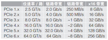
PCIe Lane and Link Speeds
PCIe compliance testing, with its own unique challenges
PCI-SIG is the developer of non-proprietary PCI technology standards and related specifications, and PCIe has now become the de facto standard for servers. PCI-SIG defines PCI specifications to support required I/O functions while being backward compatible with previous specifications. In order to enable the adoption of PCI technology throughout the industry, PCI-SIG supports both interoperability and conformance testing, including the tests that must be performed and passed to achieve conformance.
PCI-SIG allows members to interoperate against other members' products and test suites, and products that participate in the test either pass or fail the test. In order to pass the formal conformance test, the product must pass at least 80% of the interoperability test and pass all standard conformance tests.
PCIe 5.0 presents specific challenges. PCIe 4.0, with a maximum data rate of 16 GT/s, is the previous generation speed enhancement specification of PCIe and has proven to be more difficult to implement than previous standards. In PCIe 5.0, both computer PCIe lanes and motherboards face significant challenges as they deal with 32 GT/s data rates. In addition to the challenges encountered at lower data rates, PCIe 5.0 devices are expected to encounter significant signal integrity challenges. Tektronix has PCI-SIG approved test suites for all data rates (Tx, Rx and PLL bandwidth).
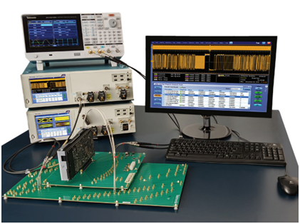
Tektronix PCIe Gen 5 Tx Compliance Test Solution
Tektronix is a major contributor to PCI-SIG, making significant contributions to PCIe 4.0 and 5.0 physical layer test specifications, and has done a lot of trail-finding experiments to determine PCIe 6.0 Tx/Rx measurement methods. Tektronix also plays a key role in conformance and interoperability testing during PCIe standard development and implementation.
PCIe 5.0 transmitter testing: Proper test equipment and automation software are critical
When developing a PCIe Gen 5 transmitter device, either at the base (chip) level or at the CEM (system and plug-in) level, chip-level validation (usually performed by the PHY IP company) and pre-compliance testing will be required before the device can be submitted to the PCI-SIG for formal compliance testing. Therefore, it is critical to have access to the appropriate test equipment and associated automation software.
PCIe compliance testing includes:
● Electrical Test - Evaluation Platform, Plug-in Transmitter (Tx) and Receiver (Rx) Features
● Configuration testing - Evaluates the configuration space in PCIe devices
● Link protocol testing - Evaluates the link-level protocol characteristics of the device
● Transaction protocol testing - Evaluates the transaction-level protocol characteristics of the device
● Platform BIOS Test - Evaluates the BIOS's ability to identify and configure PCIe devices
In terms of electrical testing, it is divided into two sets of measurements, one is the basic level and the other is the CEM level. These tests are further divided into standard tests and reference tests:
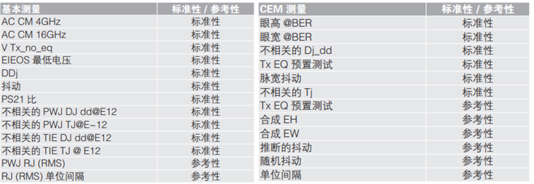
PCIe Basic and CEM Compliance Measurements
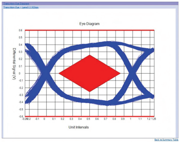
Eye Diagram
Both types of measurements require a high bandwidth real-time oscilloscope capable of capturing the data waveform. Post-processing techniques are then used to make the appropriate voltage and timing measurements required by the base and CEM specifications. Uncorrelated jitter examines the jitter inherent to the system after removing packet and channel intersymbol interference (ISI). In addition to jitter, the oscilloscope also makes eye height and eye width measurements. A number of “compliance test patterns” are specified in the base specification. It is recommended that a waveform record containing multiple occurrences of the entire compliance test pattern be used to construct a representative eye diagram.
In basic Tx testing of devices, the specification states that measurements are made directly at the pins of the transmitter. If direct access is not possible, the test points should be as close to the device pins as possible. If the user has a good understanding of the S parameters, any subsequent channel losses can be de-embedded by physically replicating the channel or by simulation. Starting with the 4.0 specification, another de-embedding technique is described, where CTLE (Continuous Time Linear Equalization) is applied to uncorrelated jitter measurements during waveform post-processing, which effectively eliminates ISI up to the pins.
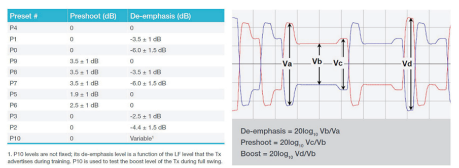
Tx EQ Presets
Any PCIe 5.0 product submitted for PCI-SIG certification must successfully pass compliance testing using the specified Tx equalizer setting presets, supporting speeds from 2.5 GT/s to 32 GT/s. These presets are used to equalize the inter-symbol interference caused by frequency-related attenuation differences within the bit stream, improving signal integrity. Each preset is a specific combination of pre-shoot (before the cursor) and de-emphasis (after the cursor).
There are various specific implementations that allow the DUT transmitter to be swept through various data rates and Tx EQ presets. However, the basic specification specifies a common method where a 100 MHz clock burst is sent to Lane 0 of the receiver. This can be automated using an arbitrary function generator (AFG).
For PCIe links with a maximum rate of 32 GT/s, new verification challenges exist for the base clocks (Refclks). The base specification already expanded the jitter limit in proportion to the data rate, but Gen5 disproportionately reduces the limit to 150 fs. This high frequency jitter measurement requires the correct application of the common clock transfer function and consideration of the worst-case transfer delay. This latest version of the specification also pushes the measurement from the base level specification (chip level) to the CEM specification requirement (surface level), which must be met for compliance testing.
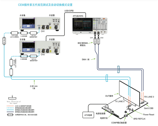
CEM plug-in PCIe 5.0 conformance test and automatic preset switching
Tektronix PCIe solution makes compliance testing more confident
Oscilloscope bandwidth and sampling rate requirements. For basic Tx testing, each PCIe 5.0 lane runs at 16 GHz (because two bits can be sent in one cycle), and the third harmonic reaches 48 GHz. Since there is not much effective signal information above the third harmonic, PCIe 5.0 basic Tx testing only requires a real-time oscilloscope with 50 GHz bandwidth. For CEM Tx testing, measurements are made near the end of the worst-case channel, reducing high-frequency content, requiring 33 GHz of bandwidth. To ensure adequate waveform post-processing (SigTest), a minimum of 4 points per unit interval is required, and CEM allows up to 2x sinx/x interpolation, so the minimum sampling rate must reach 128 GS/s.
Automated compliance testing. Performing analysis manually during compliance testing is time-consuming and error-prone. To save time, it is best to use automation software, which not only reduces the workload but also speeds up compliance testing. For electrical verification, PCI-SIG provides SigTest offline analysis software that performs analysis using data acquired by an oscilloscope. The automation software also controls the device under test (DUT) and uses an arbitrary function generator as a pattern source to automatically put the DUT through the various speeds, de-emphasis, and presets required for compliance testing.
Previous article:Keysight Technologies President of Network Applications and Security discusses how to improve security by preventing blind spots
Next article:Keysight Technologies' 5G mmWave Radio Resource Management Test Case is First to Pass PTCRB Verification
Recommended ReadingLatest update time:2024-11-16 12:51


- Popular Resources
- Popular amplifiers
- Keysight Technologies Helps Samsung Electronics Successfully Validate FiRa® 2.0 Safe Distance Measurement Test Case
- From probes to power supplies, Tektronix is leading the way in comprehensive innovation in power electronics testing
- Seizing the Opportunities in the Chinese Application Market: NI's Challenges and Answers
- Tektronix Launches Breakthrough Power Measurement Tools to Accelerate Innovation as Global Electrification Accelerates
- Not all oscilloscopes are created equal: Why ADCs and low noise floor matter
- Enable TekHSI high-speed interface function to accelerate the remote transmission of waveform data
- How to measure the quality of soft start thyristor
- How to use a multimeter to judge whether a soft starter is good or bad
- What are the advantages and disadvantages of non-contact temperature sensors?
- Innolux's intelligent steer-by-wire solution makes cars smarter and safer
- 8051 MCU - Parity Check
- How to efficiently balance the sensitivity of tactile sensing interfaces
- What should I do if the servo motor shakes? What causes the servo motor to shake quickly?
- 【Brushless Motor】Analysis of three-phase BLDC motor and sharing of two popular development boards
- Midea Industrial Technology's subsidiaries Clou Electronics and Hekang New Energy jointly appeared at the Munich Battery Energy Storage Exhibition and Solar Energy Exhibition
- Guoxin Sichen | Application of ferroelectric memory PB85RS2MC in power battery management, with a capacity of 2M
- Analysis of common faults of frequency converter
- In a head-on competition with Qualcomm, what kind of cockpit products has Intel come up with?
- Dalian Rongke's all-vanadium liquid flow battery energy storage equipment industrialization project has entered the sprint stage before production
- Allegro MicroSystems Introduces Advanced Magnetic and Inductive Position Sensing Solutions at Electronica 2024
- Car key in the left hand, liveness detection radar in the right hand, UWB is imperative for cars!
- After a decade of rapid development, domestic CIS has entered the market
- Aegis Dagger Battery + Thor EM-i Super Hybrid, Geely New Energy has thrown out two "king bombs"
- A brief discussion on functional safety - fault, error, and failure
- In the smart car 2.0 cycle, these core industry chains are facing major opportunities!
- The United States and Japan are developing new batteries. CATL faces challenges? How should China's new energy battery industry respond?
- Murata launches high-precision 6-axis inertial sensor for automobiles
- Ford patents pre-charge alarm to help save costs and respond to emergencies
- New real-time microcontroller system from Texas Instruments enables smarter processing in automotive and industrial applications
- TI reference circuit solution for electric vehicle power management
- S digital receiving channel architecture
- Sub-library: Motion Algorithm Library
- TI radar technology is changing three trends in the in-cockpit sensing market
- Prize-giving event: Blind box delivery | Murata’s Pet Pink Month is officially launched!
- AD packaging for self-use HR911105A 100M and HR911130A 1000M network ports
- Serial port expansion
- HR made inappropriate remarks in the circle of friends, made a public apology, and was fired!
- 【AT-START-F425 Review】No.02 AT32F425 Development Environment Construction
- About the use of AWR1642BOOST development system


 Wireless Sensor Network Technology and Applications (Edited by Mou Si, Yin Hong, and Su Xing)


 京公网安备 11010802033920号