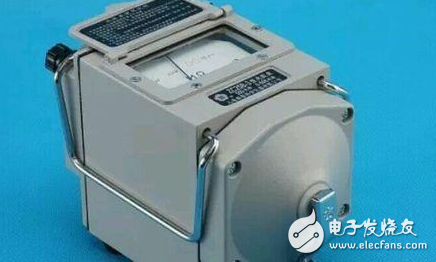
1. Use of megohmmeter (insulation resistance meter)
(1) Calibration. Before measuring, the megohmmeter should be subjected to an open circuit and short circuit test to check whether it is in good condition. Open the two connecting wires, shake the handle, and the pointer should point to "∞". Short-circuit the two connecting wires again, and the pointer should point to "0". If the above conditions are met, it is good, otherwise it cannot be used.
(2) The device under test is disconnected from the circuit, and large-capacitance devices must also be discharged.
(3) Select a megohmmeter that meets the voltage level.
(4) When measuring insulation resistance, generally only the "L" and "E" terminals are used. However, when measuring the insulation resistance of the cable to the ground or the leakage current of the device under test is serious, the "G" terminal should be used and connected to the shielding layer or the shell. After the line is connected, the crank can be turned clockwise. The speed of shaking should be from slow to fast. When the speed reaches about 120 revolutions per minute (ZC-25 model), keep the rotation at a constant speed and read the reading after 1 minute. The reading should be read while shaking, and it cannot be stopped to read.

(5) Discharge by removing the wires. After the readings are completed, slowly shake the meter while removing the wires, and then discharge the device under test. The discharge method is to remove the ground wire used during measurement from the megohmmeter and short-circuit it with the device under test (not megohmmeter discharge).
2. Measurement steps of megohmmeter (insulation resistance meter)
The use of the shake meter is divided into the following steps:
(1) Power off, test and discharge the equipment under test;
(2) Select a suitable megohmmeter according to the device under test;
(3) Check the megohmmeter, which can be divided into open circuit check and short circuit check. For open circuit, the two test leads are not in contact, the handle is turned at a constant speed, and the pointer points to infinity. For short circuit check, the handle is turned at a constant speed, the two test leads are in contact, and the pointer points to zero.
(4) First, connect section E to the ground, rotate the crank at a constant speed to 120 revolutions per minute, and then connect section L to the circuit;
(5) After measurement, discharge.
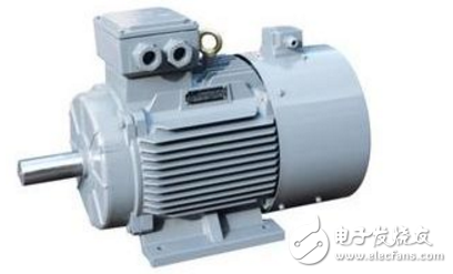
3. How to use a megohmmeter to measure the quality of a motor
First, measure the motor to ground, remove the connecting piece in the motor junction box (to ensure that each winding is independent), and connect one wire of the megohmmeter to the housing. Connect another wire to the three winding heads of the motor for measurement. It is normal if the resistance is greater than 1M. Then measure the insulation between the three windings, that is, connect one wire of the megohmmeter to one of the heads of the motor winding, and another wire to the head or tail of another winding (it is normal if the resistance is greater than 1M), then loosen one of the measuring wires of the megohmmeter, and connect it to the head or tail of the third group (unmeasured) of the motor for measurement (it is normal if the resistance is greater than 1M).

Cut off the power supply. Secondly, open the wiring and remove the terminal board connector. Third, connect the megger L to the head of any winding under the terminal board and set it as phase A, and connect E to the upper terminal. Gently shake the megger to find out the three phases ABC in turn. If there is any failure, the phase is broken. Fourth, measure the interphase insulation of the three phases ABC. The megger speed is 120 revolutions per minute. If the reading is above 0.5, it can be used. If it is less than 0.5, the insulation is damaged. Fifth, connect the first or last phase of the winding to L, and connect E to the shell. If the insulation resistance is above 0.5, it is good.
First, use a multimeter to measure the DC resistance of the three-phase winding. [In fact, the resistance of the winding is very small, and our ordinary meter can basically not tell the size, unless it is a very small motor, just check whether it is connected.]
Second, if the three-phase windings are all connected, use one wire of the megger to connect to the motor casing, and use the other wire to measure whether the resistance of the three-phase windings to the ground is normal. [The minimum resistance value must not be less than 0.5 megohms]
3. If the resistance of the three-phase winding to ground is normal, the last step is to measure the phase-to-phase insulation resistance. Connect one wire of the megohmmeter to the terminal of one phase winding, and the other wire to the other two terminals. [Note: do not connect two wires at the same time, connect them separately]. After the measurement, swap the megohmmeter wires to measure the other two phases of the winding. [During the phase-to-phase measurement, only the upper or lower three terminals need to be measured, and the resistance must not be lower than 0.5 megohms].
Clamp one of the two test leads of the megger on the terminal of the junction box and the other on the outer casing, shake the handle of the megger evenly, and the reading obtained is the insulation resistance of the motor to the ground, which is generally qualified at around 200K~2M. Clamp the two test leads of the megger on the terminals of different phases of the junction box respectively, shake the handle of the megger evenly, and the reading obtained is the insulation resistance between the phases of the motor. Generally, it is qualified when it is above 100K.
Previous article:What are the methods for identifying thermocouples and thermal resistors?
Next article:Measuring speed control motors with Fluke 87V
- Popular Resources
- Popular amplifiers
- Keysight Technologies Helps Samsung Electronics Successfully Validate FiRa® 2.0 Safe Distance Measurement Test Case
- From probes to power supplies, Tektronix is leading the way in comprehensive innovation in power electronics testing
- Seizing the Opportunities in the Chinese Application Market: NI's Challenges and Answers
- Tektronix Launches Breakthrough Power Measurement Tools to Accelerate Innovation as Global Electrification Accelerates
- Not all oscilloscopes are created equal: Why ADCs and low noise floor matter
- Enable TekHSI high-speed interface function to accelerate the remote transmission of waveform data
- How to measure the quality of soft start thyristor
- How to use a multimeter to judge whether a soft starter is good or bad
- What are the advantages and disadvantages of non-contact temperature sensors?
- LED chemical incompatibility test to see which chemicals LEDs can be used with
- Application of ARM9 hardware coprocessor on WinCE embedded motherboard
- What are the key points for selecting rotor flowmeter?
- LM317 high power charger circuit
- A brief analysis of Embest's application and development of embedded medical devices
- Single-phase RC protection circuit
- stm32 PVD programmable voltage monitor
- Introduction and measurement of edge trigger and level trigger of 51 single chip microcomputer
- Improved design of Linux system software shell protection technology
- What to do if the ABB robot protection device stops
- Allegro MicroSystems Introduces Advanced Magnetic and Inductive Position Sensing Solutions at Electronica 2024
- Car key in the left hand, liveness detection radar in the right hand, UWB is imperative for cars!
- After a decade of rapid development, domestic CIS has entered the market
- Aegis Dagger Battery + Thor EM-i Super Hybrid, Geely New Energy has thrown out two "king bombs"
- A brief discussion on functional safety - fault, error, and failure
- In the smart car 2.0 cycle, these core industry chains are facing major opportunities!
- The United States and Japan are developing new batteries. CATL faces challenges? How should China's new energy battery industry respond?
- Murata launches high-precision 6-axis inertial sensor for automobiles
- Ford patents pre-charge alarm to help save costs and respond to emergencies
- New real-time microcontroller system from Texas Instruments enables smarter processing in automotive and industrial applications
- [Review of SGP40] Rapid deployment of AI ambient air quality tracking model #1 Unboxing
- What is a NB-IoT card?
- [RVB2601 Creative Application Development] Part 2 Development Preparation 2 (Development Environment Setup and Helloworld Example)
- Comparison of technical performance between 433MHz solution and 2.4G, micro-power, and direct sequence spread spectrum solutions
- EEWORLD University Hall----Mathematical Linear System Theory
- IIS2ICLX 2-axis digital inclinometer test
- [Fudan Micro FM33LG0 Series Development Board Review] Development Environment First
- OpenRGB, an open-source lighting control that does not rely on manufacturer software
- I recently took apart an old spectrum analyzer Advantest R4131D.
- [2022 Digi-Key Innovation Design Competition] Material Unboxing STM32F750DK, etc.

 INA155EA/250


 京公网安备 11010802033920号