Last time we talked about using an oscilloscope to measure the signal of the car's air flow meter. This time we will talk about using an oscilloscope to measure the car's oxygen sensor. The oxygen sensor is also called a λ (Lambda) sensor. Compared with the air flow meter sensor, although both have an impact on the injection amount, their functions are different.
The air flow meter is mainly used to control and detect the intake volume of the automobile engine. The engine computer mainly calculates the amount of fuel injection based on this signal, which is the main signal for calculating the amount of fuel injection. The oxygen sensor is used to check the result after the injector injects fuel, whether it injects too much or too little. If it injects too much, the computer will reduce the amount of fuel injection based on this signal. If it injects too little, the computer will increase the amount of fuel injection, mainly to reduce engine emissions and prevent excessive pollution of the engine.
The oxygen sensors on cars are generally divided into zirconium oxygen and titanium oxygen. The zirconium dioxide oxygen sensor reflects the change of the concentration of the combustible mixture through the change of voltage, while the titanium dioxide oxygen sensor reflects the change of the combustible mixture through the change of resistance. The oxygen sensors used in the early days were heated by exhaust gas, and this type of sensor must start working after the engine is started and running for several minutes. Now, most cars use oxygen sensors with heaters. This type of sensor has an electric heating element inside, which can quickly heat the oxygen sensor to the operating temperature after the engine is started.
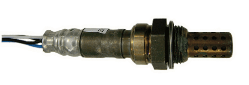
Today we will teach you how to use an oscilloscope to measure the oxygen sensor signal of a zirconium oxygen sensor with a heater. The following figure shows an oxygen sensor with a heater:

You can see that this oxygen sensor has a total of four wires, of which two black wires are the positive and negative poles of the heater element, the blue wire is the sensor signal, and the white wire is the sensor ground. There will be differences between different manufacturers, so remember to check the relevant information when measuring.
By measuring with an oscilloscope, it is possible to check whether the oxygen sensor's heating element and the control via the engine control module (ECM) are working properly.
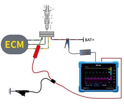
Here's how to connect the oscilloscope:

Connect one of the channels of the oscilloscope to the current probe and clamp the current clamp on one of the black lines of the oxygen sensor to measure the heater current signal. The figure shows channel 3.
Connect another channel of the oscilloscope to a BNC to banana cable, then connect a needle and an alligator clip. The alligator clip is grounded, and the needle detects the blue sensor signal line. The connection in the figure is channel 2.
Here is a sample waveform:

Channel three shows the heater current signal, which is a pulse width modulated (PWM) or square wave type signal. As the temperature rises, the resistance of the heater increases. The voltage to the heater is the constant battery voltage from the ECM (which is the value measured by channel one in the figure), so as the resistance of the heater increases, the current will decrease. The most important feature of this waveform is not the height of the current pulses, but their width. The engine's ECM controls the energy to the heater by adjusting the width of each pulse.
Channel 2 displays the voltage signal of the sensor, which represents the oxygen content in the exhaust gas.
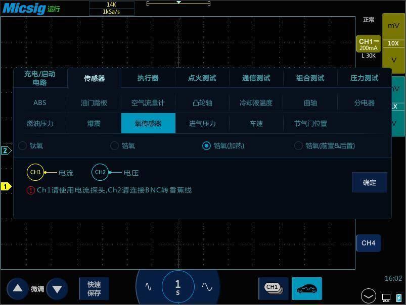
If you are using an ATO series oscilloscope, you can open the car package and directly select the corresponding measurement item sensor-oxygen sensor-zirconium oxygen (heating) to automatically complete the oscilloscope settings.

Previous article:Rigol DAS4052 Digital Oscilloscope Operation Introduction
Next article:Oscilloscope ignition signal waveform analysis
- Popular Resources
- Popular amplifiers
-
 Multisim Circuit System Design and Simulation Tutorial
 -
 A_2.89_uW_Dry-Electrode_Enabled_Clockless_Wireless_ECG_SoC_for_Wearable_Applications
 -
 Model Engineering in Mixed-Signal Circuit Design: A Guide to Generating...
 -
 A 10.1” 183-μWelectrode, 0.73-mm2sensor High-SNR 3-D Hover Sensor Based on Enhanced Signal Refining
- New IsoVu™ Isolated Current Probes: Bringing a New Dimension to Current Measurements
- Modern manufacturing strategies drive continuous improvement in ICT online testing
- Methods for Correlation of Contact and Non-Contact Measurements
- Keysight Technologies Helps Samsung Electronics Successfully Validate FiRa® 2.0 Safe Distance Measurement Test Case
- From probes to power supplies, Tektronix is leading the way in comprehensive innovation in power electronics testing
- Seizing the Opportunities in the Chinese Application Market: NI's Challenges and Answers
- Tektronix Launches Breakthrough Power Measurement Tools to Accelerate Innovation as Global Electrification Accelerates
- Not all oscilloscopes are created equal: Why ADCs and low noise floor matter
- Enable TekHSI high-speed interface function to accelerate the remote transmission of waveform data
- Intel promotes AI with multi-dimensional efforts in technology, application, and ecology
- ChinaJoy Qualcomm Snapdragon Theme Pavilion takes you to experience the new changes in digital entertainment in the 5G era
- Infineon's latest generation IGBT technology platform enables precise control of speed and position
- Two test methods for LED lighting life
- Don't Let Lightning Induced Surges Scare You
- Application of brushless motor controller ML4425/4426
- Easy identification of LED power supply quality
- World's first integrated photovoltaic solar system completed in Israel
- Sliding window mean filter for avr microcontroller AD conversion
- What does call mean in the detailed explanation of ABB robot programming instructions?
- STMicroelectronics discloses its 2027-2028 financial model and path to achieve its 2030 goals
- 2024 China Automotive Charging and Battery Swapping Ecosystem Conference held in Taiyuan
- State-owned enterprises team up to invest in solid-state battery giant
- The evolution of electronic and electrical architecture is accelerating
- The first! National Automotive Chip Quality Inspection Center established
- BYD releases self-developed automotive chip using 4nm process, with a running score of up to 1.15 million
- GEODNET launches GEO-PULSE, a car GPS navigation device
- Should Chinese car companies develop their own high-computing chips?
- Infineon and Siemens combine embedded automotive software platform with microcontrollers to provide the necessary functions for next-generation SDVs
- Continental launches invisible biometric sensor display to monitor passengers' vital signs
- Symbols for resistor rated power values on circuit diagrams
- [Telink's new generation of low-power, high-performance, multi-protocol wireless kit B91 review] Zigbee program generation and compilation configuration
- Chatting about Saifang: Linux mainline officially supports Saifang JH7100 chip, how did you do it?
- Electronic Measurement Course Self-Study Guide
- Drop down list box problem
- [STM32F769Discovery development board trial] Build development environment & drive LCD screen to display dot matrix characters & touch screen driver
- Chuanglong TMS320C6748 development board——UART register introduction and program
- What is the use of C language? Is it easy to learn?
- Notice: "ST MEMS Sensor Technology Forum" is renamed "ST Sensor and Low Power Wireless Technology Forum"
- Supply LED constant current IC

 Multisim Circuit System Design and Simulation Tutorial


 京公网安备 11010802033920号