NI LabVIEW software and PXI hardware were used to measure every input and output signal of the engine and the simulated biomass gas fuel generator.
Biomass gas is produced by fermentation and pyrolysis of organic matter, in which combustible gases (such as methane, hydrogen, and carbon monoxide) are mixed with non-combustible gases (such as carbon dioxide and nitrogen). The gas mixture ratio varies depending on the type of biomass resource used as raw material or the gasification method, as well as changes caused by temperature fluctuations in the fuel generator. In addition, biomass gas contains gases with low calorific values (hydrogen and carbon monoxide) and non-combustible gases (carbon dioxide and nitrogen), so its calorific value is lower than that of gas fuel sold on the market, which may cause many problems when the engine is running.
In order to develop a biomass gas fuel engine, we must understand how the differences in fuel calorific value and gas composition affect the engine's operating conditions. We completed a combustion analysis of simulated biomass gas fuel on an experimental engine. As the first step in the development of a biomass gas fuel engine, the simulated biomass gas fuel used was a mixture of multiple gas components in random proportions.
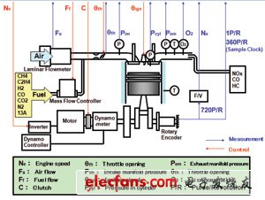
In the engine operation experiment, the simulated biomass gas fuel generator provides the engine with simulated biomass gas fuel, and the data acquisition equipment collects experimental data.

Figure 1 Schematic diagram of the experimental setup
When using these devices to conduct engine operation experiments, synchronous measurement of signals and improving mechanical operation efficiency are two main challenges in the experiments.
Measurement
In order to analyze and evaluate the impact of differences in fuel gas composition on the necessary conditions for engine operation, we measure a large amount of data, such as fuel and air flow rates as well as temperature and pressure at various points in the engine while the engine is running. It is important to synchronize the measurements with the movement of the engine crankshaft to facilitate subsequent analysis. The sampling rate needs to be flexible: the pressure signal changes rapidly, so we sample once per degree of crankshaft rotation (9000Hz is required for an engine with a rated speed of 1500rpm); the temperature changes relatively slowly, so we sample once per crankshaft revolution. In addition, the output voltage signal varies depending on the sensor amplifier; therefore, we set each channel to obtain accurate measurements.
Engine operation control
When starting the engine, we must connect the clutch, turn the self-starting motor, and disconnect the clutch when the fuel supply is established. Furthermore, during the operation of the engine, we must use actuators (such as valves, mass flow controllers, and spark plugs) to adjust the air and fuel flow and ignition timing to achieve the experimental conditions set in advance. Operating multiple devices at the same time and monitoring the engine operating conditions during the experiment is a big hassle for experimenters, and improving efficiency is very necessary.
Generate simulated biomass gas
Seven biomass flow controllers independently monitor and control the flow of six types of gases (CH4, C2H4, H2, CO, CO2, and N2) and a tank of commercially available 13A gas. Therefore, we have to control seven controllers simultaneously to generate simulated biomass gas with any mixing ratio, which is a complicated process.
system structure
In order to control seven controllers at the same time, we used NI products in all input/output interfaces of the engine measurement equipment and the simulated biomass gas fuel generator, and built the engine measurement control system and the simulated biomass gas fuel generation system. We used LabVIEW for software development of both systems.
The engine measurement and control system uses an NI PXI-8176 controller, a PXI-6071E analog input multifunction data acquisition (DAQ) module, a PXI-6733 high-speed analog output module, and a PXI-6602 timing and digital I/O module. For measurement, the PXI-6071E is used to sample the sensor output at each crankshaft angle based on the signal from the rotary encoder. For operation control, we use the PXI-6733 module to operate various actuators such as the clutch, self-starting motor, throttle, and mass flow controller; and the PXI-6602 is used to generate the ignition signal. NI hardware unifies the signals of the I/O of various devices that need to be operated when running the engine. Our system built with PCs can run the engine and perform various measurements.
To develop a simulated biomass gas fuel generation system, we used a commercial desktop PC and PXI chassis, a PXI-6031E analog input multifunction DAQ module, and a PXI-6733 module. The voltage input from the PXI-6733 controls the flow rate of each gas component, and the PXI-6031E measures the actual flow rate. The PC synchronously controls seven mass flow controllers, allowing the system to control the gas components to produce any mixing ratio.
Results
In terms of measurement, we have successfully achieved synchronous sampling of the engine crankshaft movement. In addition, the sampling rate and measurement range of each channel can be easily set using software. The test can be completed using only a PC, which simplifies the test operation.
We also use LabVIEW to analyze data. All work from experiment to analysis can be done with LabVIEW. Since there is no need to mix programming in multiple languages, it further saves time.
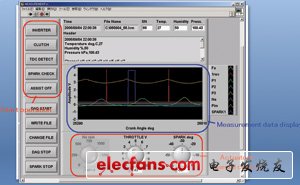
Figure 2(a) is the engine measurement control program, which has the functions of automatically processing the engine start procedure, manually controlling and adjusting the actuators to the experimental conditions, and measuring the experimental data.

Figure 2(a) Engine measurement control
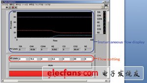
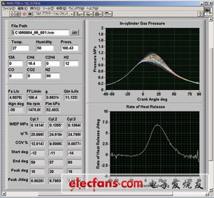
Figure 2(b) shows the front panel of the program for setting the simulated biomass gas fuel mixture ratio, which can set and monitor the flow rates of the seven gases. We use these data to analyze the engine performance, including output power, thermal efficiency, output power variation coefficient, and combustion characteristics (such as combustion start time and combustion duration). The analysis program used is shown in Figure 3.

Figure 2(b) Front panel of the program for setting the simulated biomass gas fuel mixing ratio

Figure 3 Analysis
in conclusion
Using LabVIEW, we successfully built a measurement control system for a biomass gas fuel engine. The software we used to build the system provided flexible settings and could handle a large number of I/O signals, which greatly reduced the experimental time. In addition, the entire process from measurement to analysis used LabVIEW, which improved our efficiency. Finally, when we built a biomass gas fuel engine control system based on the experiment, we only needed to change the software to implement the new system, thereby improving the efficiency of further development.
Previous article:LabVIEW FPGA and software design RF instrument advantages detailed explanation
Next article:Thermal Comfort Test System Solution Using LabVIEW
- Popular Resources
- Popular amplifiers
- Keysight Technologies Helps Samsung Electronics Successfully Validate FiRa® 2.0 Safe Distance Measurement Test Case
- From probes to power supplies, Tektronix is leading the way in comprehensive innovation in power electronics testing
- Seizing the Opportunities in the Chinese Application Market: NI's Challenges and Answers
- Tektronix Launches Breakthrough Power Measurement Tools to Accelerate Innovation as Global Electrification Accelerates
- Not all oscilloscopes are created equal: Why ADCs and low noise floor matter
- Enable TekHSI high-speed interface function to accelerate the remote transmission of waveform data
- How to measure the quality of soft start thyristor
- How to use a multimeter to judge whether a soft starter is good or bad
- What are the advantages and disadvantages of non-contact temperature sensors?
- LED chemical incompatibility test to see which chemicals LEDs can be used with
- Application of ARM9 hardware coprocessor on WinCE embedded motherboard
- What are the key points for selecting rotor flowmeter?
- LM317 high power charger circuit
- A brief analysis of Embest's application and development of embedded medical devices
- Single-phase RC protection circuit
- stm32 PVD programmable voltage monitor
- Introduction and measurement of edge trigger and level trigger of 51 single chip microcomputer
- Improved design of Linux system software shell protection technology
- What to do if the ABB robot protection device stops
- Allegro MicroSystems Introduces Advanced Magnetic and Inductive Position Sensing Solutions at Electronica 2024
- Car key in the left hand, liveness detection radar in the right hand, UWB is imperative for cars!
- After a decade of rapid development, domestic CIS has entered the market
- Aegis Dagger Battery + Thor EM-i Super Hybrid, Geely New Energy has thrown out two "king bombs"
- A brief discussion on functional safety - fault, error, and failure
- In the smart car 2.0 cycle, these core industry chains are facing major opportunities!
- The United States and Japan are developing new batteries. CATL faces challenges? How should China's new energy battery industry respond?
- Murata launches high-precision 6-axis inertial sensor for automobiles
- Ford patents pre-charge alarm to help save costs and respond to emergencies
- New real-time microcontroller system from Texas Instruments enables smarter processing in automotive and industrial applications
- "Hello, DSP world" project example for DSP primary programming
- Boot Sector (Boot Block) in Nor Flash
- 【RPi PICO】MicroPython driving ws2812
- The 5 yuan multimeter has arrived
- A Simple Comparison of LoRa Technology and NB-IoT
- Boa application-web page configuration domestic A40i development board
- How to use the instruction MOV C, P1.1? There is no instruction MOV C, XX in the 51 assembly instruction table.
- Working hours of heart rate bracelet
- A great popular science article on electromagnetic compatibility principles, methods and design!
- [GD32L233C] + 1. Unboxing & Development Environment Setup

 ICL7621AMTV/C


 京公网安备 11010802033920号