USB Introduction
USB (Universal Serial Bus) is a universal serial bus used to connect peripheral devices such as keyboards, mice, printers, scanners, digital cameras, MP3, and USB flash drives to computers. It standardizes the interface between computers and peripheral devices. The USB1.1 version supports two speeds: full-speed 12Mbps and low-speed 1.5Mbps; while USB2.0 supports three speeds: high-speed 480Mbps, full-speed 12Mbps, and low-speed 1.5Mbps. In 2002, Intel integrated the USB2.0 port into the computer's south bridge chip ICH4, which promoted the popularization of USB2.0. Currently, except for keyboards and mice, which are low-speed devices, most devices are high-speed devices with a speed of 480M.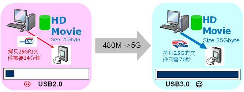
Figure 1: Speed comparison between USB 2.0 and USB 3.0
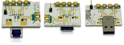
Figure 2: LeCroy's USB 3.0 test fixture
USB3.0 physical layer test content
LeCroy's latest version of consistency test software QualiPHY-USB3 is developed based on the USB3.0 Electrical Compliance Test Specification Rev0.9 released in November 2009, and will be continuously updated as the test specification is updated. The software is installed on an oscilloscope, which is connected to PeRT3 via a USB cable and communicates with PeRT3 using USB. During the test, QualiPHY software can control PeRT3 to send specific signals or read RX test results from PeRT3, so that only QualiPHY software can complete all TX and RX tests. The following test items are included in the QualiPHY-USB3 test software:
1. LFPS (Low Frequency Periodic Signaling) signal measurement
2. SSC (Spread Spectrum Clock) spread spectrum measurement
3. Jitter and eye diagram measurement
4. AC and DC common mode voltage measurement
5. Differential voltage amplitude and de-emphasis measurement
6. Error test and jitter tolerance measurement
LFPS (Low Frequency Periodic Signaling) signal measurement
Measured the voltage and time parameters of Polling.LFPS signaling, which is a mandatory test item in the USB3.0 specification CTS Rev0.9. The test method is: insert a USB3.0 fixture into the port of the product to be tested (PUT), and the TX end on the fixture is connected to the two channels of the oscilloscope through a coaxial cable. After the PUT is powered on, the PUT will send out Polling.LFPS signaling, and the oscilloscope will capture and measure its horizontal or vertical parameters. Figure 3 shows the signal characteristics of LFPS. In the LeCroy consistency test software, the pulse rise and fall time, period, duty cycle, peak-to-peak value, common mode voltage, and the burst duration (tBurst) and repetition time (tRepeat) of the pulse train are analyzed.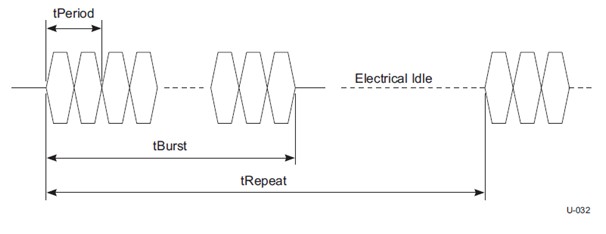
SSC is often used in computer motherboard circuits to reduce electromagnetic radiation. In USB3.0, it is necessary to test the modulation frequency (SSC Modulate Rate), maximum frequency deviation (SSC Deviation Max) and minimum frequency deviation (SSC Deviation Min) of the spread spectrum clock. During the test, the PUT sends a data stream with a CP1 code (CP is the abbreviation of Compliance Pattern. In the physical layer test of USB3, different test codes are required for each test). The CP1 code is D10.2, that is, a code of continuous jumps of 0101, which is equivalent to a clock frequency of 2.5GHz. The specification requires that the modulation frequency of the spread spectrum clock be between 30-33KHz, the minimum frequency deviation be between +/-300ppm, and the maximum frequency deviation be between -5300ppm and -3700ppm. Figure 4 shows the result of measuring the spread spectrum clock with a LeCroy oscilloscope. SSC is a mandatory test item in CTS Rev0.9 and is closely related to the USB3.0 chip input clock. If the SSC of the input clock does not meet the requirements, the SSC of the USB3.0 output signal will usually fail the test.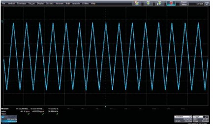
Figure 4: Spread spectrum clock test results
Jitter and eye diagram measurement
In the eye diagram and jitter test of USB3.0 TX, the eye diagram and jitter of the TP1 point after the signal to be tested passes through the reference test channel are measured. The Reference test channel in Figure 5 is the reference test channel. The specification defines three reference test channels: long channel, short channel and 3-meter cable. If a long channel or a long cable is used, the signal will be greatly attenuated when it reaches the receiving end, and the eye diagram will be closed. After the USB3.0 chip receiving end uses a CTLE equalizer to equalize the signal, the quality of the signal eye diagram will be greatly improved, so the test instrument is required to analyze the eye diagram and jitter of the signal after the CTLE equalizer is processed. Currently, Intel's 11-inch backplane and 3-meter USB cable are commonly used as reference channels in the industry.
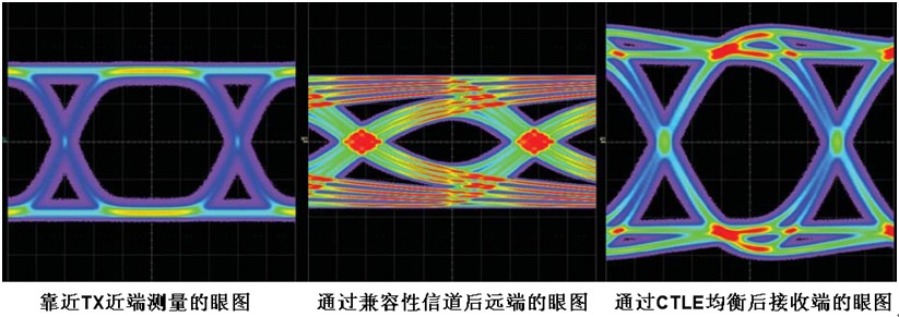
Figure 6: USB 3.0 Transmitter test eye diagram comparison at near end, far end and after equalization
The signal source needs to send out special test patterns in the eye diagram and jitter test. For the eye diagram test, the CP0 pattern (scrambled D0.0) is required. For the jitter test, the CP0 code stream or CP1 code stream (D10.2) is required. The former is used to measure the deterministic jitter Dj, and the latter is used to measure the random jitter Rj. The eye height must be measured from the eye diagram of 1 million bits superimposed continuously. The LeCroy SDA813Zi oscilloscope only takes 2 seconds to complete the eye diagram of 1 million bits, which is 10-50 times faster than similar oscilloscopes. The peak-to-peak value of jitter when the jitter is 10e-12 bit error rate (i.e., the total jitter Tj).
AC and DC common mode voltage measurement
This test requires the PUT to send the CP0 code stream and measure the AC and DC common mode voltages of the differential signal, which is required in USB3.0 Specification Rev1.0 (the former Vtx-ac-cm-pp <= 0.1V, the latter Vtx-dc-cm between 0-2.2V), but not required in the USB3.0 compatibility test specification CTS Rev0.9.
Differential voltage amplitude and de-emphasis measurement
The purpose of the differential voltage swing test is to verify whether the peak-to-peak value of the signal is between 0.8-1.2V. In the test, the PUT needs to send the test code CP8, which consists of 50-250 consecutive 1s and 50-250 consecutive 0s repeated alternately, and the de-emphasis is eliminated. Its waveform is equivalent to a clock divided by 50-250. In these tests, the measurement results are more accurate after the USB3.0 test fixture is de-embedded.
In order to transmit 5Gbps data over a longer distance, the USB3.0 transmitter uses de-emphasis technology. This test can measure whether the de-emphasis of the PUT meets the specification requirements (required to be between -3dB and -4dB). During the test, the DUT sends out a CP7 code stream. The CP7 code type consists of 50-250 consecutive 1s and 50-250 consecutive 0s repeated alternately, and it is a signal waveform with de-emphasis added. The USB3.0 compatibility test specification CTS Rev0.9 does not require differential voltage amplitude and de-emphasis measurement.
Error and jitter tolerance test
Since the USB3.0 rate is as high as 5Gbps, the receiver test becomes a must-test item in the USB3.0 specification. The receiver test includes two parts: error and jitter tolerance test.
Keywords:USB3.0
Reference address:Discussion on Physical Layer Test of USB3.0
USB (Universal Serial Bus) is a universal serial bus used to connect peripheral devices such as keyboards, mice, printers, scanners, digital cameras, MP3, and USB flash drives to computers. It standardizes the interface between computers and peripheral devices. The USB1.1 version supports two speeds: full-speed 12Mbps and low-speed 1.5Mbps; while USB2.0 supports three speeds: high-speed 480Mbps, full-speed 12Mbps, and low-speed 1.5Mbps. In 2002, Intel integrated the USB2.0 port into the computer's south bridge chip ICH4, which promoted the popularization of USB2.0. Currently, except for keyboards and mice, which are low-speed devices, most devices are high-speed devices with a speed of 480M.

Figure 1: Speed comparison between USB 2.0 and USB 3.0
Although the speed of USB2.0 is quite fast, it is still a bit slow for the data transmission of current Blu-ray DVD, high-definition video, and TB-level large-capacity hard disks. Therefore, in November 2008, HP, Intel, Microsoft, NEC, ST-NXP, and TI jointly released the V1.0 specification of USB3.0. USB3.0 is also called SuperSpeed USB, with a bit rate of up to 5Gbps, which is more than 10 times higher than the current 480Mbps rate of USB2.0. As shown in Figure 1: It takes 14 minutes to copy a 25GB file using USB2.0, while 3.0 only takes about 70 seconds. 25GB is exactly the capacity of a single-sided single-layer Blu-ray disc. USB3.0 is expected to be gradually used in computers and consumer electronics products in 2011.
LeCroy released the physical layer test solution for USB3.0 in April 2009, including the transmitter (TX) test and receiver (RX) test for HOST/DEVICE, as well as the TDR test of USB3.0 cable. For the TX test of USB3.0, in order to measure the 5th harmonic, an oscilloscope with a bandwidth of more than 12.5GHz is required. LeCroy's SDA813Zi has a bandwidth of 13GHz and a sampling rate of 40GSamples/s (up to 80GS/s). With the USB3.0 compliance test software QualiPHY, Eye Doctor software and test fixture (see Figure 2), the transmitter compliance test and debugging analysis of USB3.0 can be completed quickly. For the RX test of USB3.0, LeCroy's PeRT3 is a bit error rate tester with protocol communication capabilities, which can complete the bit error and jitter tolerance test of USB3.0. The USB3.0 specification requires simultaneous measurement of TX and RX.

Figure 2: LeCroy's USB 3.0 test fixture
LeCroy's latest version of consistency test software QualiPHY-USB3 is developed based on the USB3.0 Electrical Compliance Test Specification Rev0.9 released in November 2009, and will be continuously updated as the test specification is updated. The software is installed on an oscilloscope, which is connected to PeRT3 via a USB cable and communicates with PeRT3 using USB. During the test, QualiPHY software can control PeRT3 to send specific signals or read RX test results from PeRT3, so that only QualiPHY software can complete all TX and RX tests. The following test items are included in the QualiPHY-USB3 test software:
1. LFPS (Low Frequency Periodic Signaling) signal measurement
2. SSC (Spread Spectrum Clock) spread spectrum measurement
3. Jitter and eye diagram measurement
4. AC and DC common mode voltage measurement
5. Differential voltage amplitude and de-emphasis measurement
6. Error test and jitter tolerance measurement
LFPS (Low Frequency Periodic Signaling) signal measurement
Measured the voltage and time parameters of Polling.LFPS signaling, which is a mandatory test item in the USB3.0 specification CTS Rev0.9. The test method is: insert a USB3.0 fixture into the port of the product to be tested (PUT), and the TX end on the fixture is connected to the two channels of the oscilloscope through a coaxial cable. After the PUT is powered on, the PUT will send out Polling.LFPS signaling, and the oscilloscope will capture and measure its horizontal or vertical parameters. Figure 3 shows the signal characteristics of LFPS. In the LeCroy consistency test software, the pulse rise and fall time, period, duty cycle, peak-to-peak value, common mode voltage, and the burst duration (tBurst) and repetition time (tRepeat) of the pulse train are analyzed.

Figure 3: Waveform of LFPS signal
SSC (Spread Spectrum Clock) Spread spectrum measurement SSC is often used in computer motherboard circuits to reduce electromagnetic radiation. In USB3.0, it is necessary to test the modulation frequency (SSC Modulate Rate), maximum frequency deviation (SSC Deviation Max) and minimum frequency deviation (SSC Deviation Min) of the spread spectrum clock. During the test, the PUT sends a data stream with a CP1 code (CP is the abbreviation of Compliance Pattern. In the physical layer test of USB3, different test codes are required for each test). The CP1 code is D10.2, that is, a code of continuous jumps of 0101, which is equivalent to a clock frequency of 2.5GHz. The specification requires that the modulation frequency of the spread spectrum clock be between 30-33KHz, the minimum frequency deviation be between +/-300ppm, and the maximum frequency deviation be between -5300ppm and -3700ppm. Figure 4 shows the result of measuring the spread spectrum clock with a LeCroy oscilloscope. SSC is a mandatory test item in CTS Rev0.9 and is closely related to the USB3.0 chip input clock. If the SSC of the input clock does not meet the requirements, the SSC of the USB3.0 output signal will usually fail the test.

Figure 4: Spread spectrum clock test results
In the eye diagram and jitter test of USB3.0 TX, the eye diagram and jitter of the TP1 point after the signal to be tested passes through the reference test channel are measured. The Reference test channel in Figure 5 is the reference test channel. The specification defines three reference test channels: long channel, short channel and 3-meter cable. If a long channel or a long cable is used, the signal will be greatly attenuated when it reaches the receiving end, and the eye diagram will be closed. After the USB3.0 chip receiving end uses a CTLE equalizer to equalize the signal, the quality of the signal eye diagram will be greatly improved, so the test instrument is required to analyze the eye diagram and jitter of the signal after the CTLE equalizer is processed. Currently, Intel's 11-inch backplane and 3-meter USB cable are commonly used as reference channels in the industry.

Figure 5: USB 3.0 TX eye diagram test points (from USB 3.0 specification)
As shown in Figure 6, the eye diagram on the left is the eye diagram measured near the TX near end; the eye diagram in the middle is the eye diagram measured after passing through the compatibility channel (reference test channel), and it can be seen that the eye opening is small and the jitter is large; the eye diagram on the right is the eye diagram after simulated CTLE equalization, and it can be seen that both the eye height and jitter are improved.
Figure 6: USB 3.0 Transmitter test eye diagram comparison at near end, far end and after equalization
AC and DC common mode voltage measurement
This test requires the PUT to send the CP0 code stream and measure the AC and DC common mode voltages of the differential signal, which is required in USB3.0 Specification Rev1.0 (the former Vtx-ac-cm-pp <= 0.1V, the latter Vtx-dc-cm between 0-2.2V), but not required in the USB3.0 compatibility test specification CTS Rev0.9.
Differential voltage amplitude and de-emphasis measurement
The purpose of the differential voltage swing test is to verify whether the peak-to-peak value of the signal is between 0.8-1.2V. In the test, the PUT needs to send the test code CP8, which consists of 50-250 consecutive 1s and 50-250 consecutive 0s repeated alternately, and the de-emphasis is eliminated. Its waveform is equivalent to a clock divided by 50-250. In these tests, the measurement results are more accurate after the USB3.0 test fixture is de-embedded.
In order to transmit 5Gbps data over a longer distance, the USB3.0 transmitter uses de-emphasis technology. This test can measure whether the de-emphasis of the PUT meets the specification requirements (required to be between -3dB and -4dB). During the test, the DUT sends out a CP7 code stream. The CP7 code type consists of 50-250 consecutive 1s and 50-250 consecutive 0s repeated alternately, and it is a signal waveform with de-emphasis added. The USB3.0 compatibility test specification CTS Rev0.9 does not require differential voltage amplitude and de-emphasis measurement.
Error and jitter tolerance test
Since the USB3.0 rate is as high as 5Gbps, the receiver test becomes a must-test item in the USB3.0 specification. The receiver test includes two parts: error and jitter tolerance test.
Previous article:Application of Ethernet in Lightning Surge Test
Next article:USB 3.0 Compliance Test Methodology
- Popular Resources
- Popular amplifiers
Recommended Content
Latest Test Measurement Articles
- From probes to power supplies, Tektronix is leading the way in comprehensive innovation in power electronics testing
- Seizing the Opportunities in the Chinese Application Market: NI's Challenges and Answers
- Tektronix Launches Breakthrough Power Measurement Tools to Accelerate Innovation as Global Electrification Accelerates
- Not all oscilloscopes are created equal: Why ADCs and low noise floor matter
- Enable TekHSI high-speed interface function to accelerate the remote transmission of waveform data
- How to measure the quality of soft start thyristor
- How to use a multimeter to judge whether a soft starter is good or bad
- What are the advantages and disadvantages of non-contact temperature sensors?
- In what situations are non-contact temperature sensors widely used?
MoreSelected Circuit Diagrams
MorePopular Articles
- LED chemical incompatibility test to see which chemicals LEDs can be used with
- Application of ARM9 hardware coprocessor on WinCE embedded motherboard
- What are the key points for selecting rotor flowmeter?
- LM317 high power charger circuit
- A brief analysis of Embest's application and development of embedded medical devices
- Single-phase RC protection circuit
- stm32 PVD programmable voltage monitor
- Introduction and measurement of edge trigger and level trigger of 51 single chip microcomputer
- Improved design of Linux system software shell protection technology
- What to do if the ABB robot protection device stops
MoreDaily News
- Huawei's Strategic Department Director Gai Gang: The cumulative installed base of open source Euler operating system exceeds 10 million sets
- Download from the Internet--ARM Getting Started Notes
- Learn ARM development(22)
- Learn ARM development(21)
- Learn ARM development(20)
- Learn ARM development(19)
- Learn ARM development(14)
- Learn ARM development(15)
- Analysis of the application of several common contact parts in high-voltage connectors of new energy vehicles
- Wiring harness durability test and contact voltage drop test method
Guess you like
- Qorvo Launches Industry-Leading Low Noise Figure LNA to Support 5G Base Station Deployment
- [Shijian's ADI Road Theme Tour] Second stop: Accumulate knowledge of instruments and meters, check in to win Kindle and other gifts
- How to check for broken wire errors when drawing AD schematics
- DSP embedded temperature measurement system
- Creating music with PICO
- Play with "ultra-energy-saving, high-precision, machine learning core" motion sensors [ST MEMS sensor competition]
- Using PLLs in Cyclone Devices
- 1uS wide pulse signal
- The test method of Tg value and the factors affecting it
- [Qinheng Trial] CH559EVT Trial 1: Unboxing and First Look

 TC52N4817ECTRT


 京公网安备 11010802033920号