LTE (Long Term Evolution) is the evolution of 3G and has been selected by the International Telecommunication Union as the fourth generation mobile communication (4G) standard. MORLAB has some experience in the field of LTE testing, and we will introduce LTE testing technology to you in stages.
For the multiple access scheme of the physical layer of LTE, Orthogonal Frequency Division Multiplexing (OFDM) based on cyclic prefix is used in the downlink direction, and Single Carrier Frequency Division Multiple Access (SC-FDMA) based on cyclic prefix is used in the uplink direction. In order to support paired and unpaired spectrum, frequency division duplex (FDD) mode and time division duplex (TDD) mode are supported. The TD-SCDMA currently used in China supports the time division duplex (TDD) mode, while in foreign countries, such as the United States, it supports the frequency division duplex (FDD) mode.
In reality, most applications are still in the frequency division duplex (FDD) mode, and the standard applicable to its FCC certification in the United States is FCC 47 CFR Part 27. This standard specifies that the bands to be used are LTE Band 4 and LTE Band 17. The specific test items are as follows:
(Table 1)
As shown in Table 1, there are eight LTE test items in total, of which the fourth test PAR (Peak to Average Radio) is a new test, and the other tests are similar to Part 22&24. The
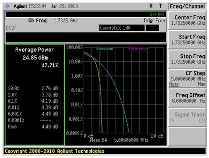
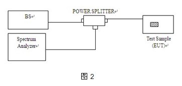
following figure is the explanation result of Peak to Average Radio. Figure 1 The specific test process is as follows: 1. First, we need to build a test system in the shielded room. The test equipment used includes a spectrum analyzer, an LTE test system, and a power divider (connect the end with large power attenuation to the spectrum analyzer) as shown in Figure 2. 2. Connect the MS (EUT). When entering the test, we must pay attention to the settings of the MS under test. In addition, we must check whether the RF line and the spectrum analyzer interface are connected properly. 3. Select the frequency center option in the spectrum analyzer to set the center frequency, and then enter Measure to set the channel bandwidth, that is, set the width of the Span (generally larger than the occupied bandwidth of the product) and the compensation value of the RF line. 4. Then enter the Power Star CCDF option of the spectrum analyzer and set the number of samples required (the number of frequency point samples). 5. After setting up the spectrum analyzer, connect the MS to the base station for communication and adjust the product to the maximum transmission power. At this time, you must remember that LTE tests have different RB (fast resource) and different modulation methods. According to the regulations of the certification agency, the combination of several situations must be tested. 6. When you see the signal coming out in the spectrum analyzer, enter the Single option and freeze the waveform. Figure 1 is the result we need. Generally speaking, the number of measurements is more than three times, and then the screenshot is saved. We can see that the ratio of the peak value to the average value at 0.1% in Figure 1 is 4.19dBm. The standard FCC stipulates that the 0.1% power ratio of PAR cannot exceed 13dBm. The early spectrum did not have the Power Star CCDF test function. It was to set a frequency band and take the power value of the mark point, and then calculate the average and peak data for comparison. Therefore, when testing, you need to save the data, and you must choose a new generation of spectrum analyzer testing. Here we only briefly introduce the test of the conduction mode of the transmitter of the LTE (FDD) product. If you want to know more about the test information, you can contact the nearest MORLAB.


Reference address:Detailed explanation of PAR (Peak to Average Radio) requirements in LTE testing
For the multiple access scheme of the physical layer of LTE, Orthogonal Frequency Division Multiplexing (OFDM) based on cyclic prefix is used in the downlink direction, and Single Carrier Frequency Division Multiple Access (SC-FDMA) based on cyclic prefix is used in the uplink direction. In order to support paired and unpaired spectrum, frequency division duplex (FDD) mode and time division duplex (TDD) mode are supported. The TD-SCDMA currently used in China supports the time division duplex (TDD) mode, while in foreign countries, such as the United States, it supports the frequency division duplex (FDD) mode.
In reality, most applications are still in the frequency division duplex (FDD) mode, and the standard applicable to its FCC certification in the United States is FCC 47 CFR Part 27. This standard specifies that the bands to be used are LTE Band 4 and LTE Band 17. The specific test items are as follows:
| No. | Section | Description |
| 1 | 2.1046 | Transmitter Conducted Output Power |
| 2 | 2.1049, 27.53 (g) | Occupied Bandwidth |
| 3 | 2.1055, 27.54 | Frequency Stability |
| 4 | 27.50(d) (5) | Peak to Average Radio |
| 5 | 2.1051, 27.53 (g) | Conducted Spurious Emissions |
| 6 | 27.53(g)(h) | Band Edge |
| 7 | 2.1046, 27.50 (d)(4) | Equivalent Isotropic Radiated Power |
| 8 | 2.1053, 27.53 (g) | Radiated Spurious Emissions |
(Table 1)
As shown in Table 1, there are eight LTE test items in total, of which the fourth test PAR (Peak to Average Radio) is a new test, and the other tests are similar to Part 22&24. The
following figure is the explanation result of Peak to Average Radio. Figure 1 The specific test process is as follows: 1. First, we need to build a test system in the shielded room. The test equipment used includes a spectrum analyzer, an LTE test system, and a power divider (connect the end with large power attenuation to the spectrum analyzer) as shown in Figure 2. 2. Connect the MS (EUT). When entering the test, we must pay attention to the settings of the MS under test. In addition, we must check whether the RF line and the spectrum analyzer interface are connected properly. 3. Select the frequency center option in the spectrum analyzer to set the center frequency, and then enter Measure to set the channel bandwidth, that is, set the width of the Span (generally larger than the occupied bandwidth of the product) and the compensation value of the RF line. 4. Then enter the Power Star CCDF option of the spectrum analyzer and set the number of samples required (the number of frequency point samples). 5. After setting up the spectrum analyzer, connect the MS to the base station for communication and adjust the product to the maximum transmission power. At this time, you must remember that LTE tests have different RB (fast resource) and different modulation methods. According to the regulations of the certification agency, the combination of several situations must be tested. 6. When you see the signal coming out in the spectrum analyzer, enter the Single option and freeze the waveform. Figure 1 is the result we need. Generally speaking, the number of measurements is more than three times, and then the screenshot is saved. We can see that the ratio of the peak value to the average value at 0.1% in Figure 1 is 4.19dBm. The standard FCC stipulates that the 0.1% power ratio of PAR cannot exceed 13dBm. The early spectrum did not have the Power Star CCDF test function. It was to set a frequency band and take the power value of the mark point, and then calculate the average and peak data for comparison. Therefore, when testing, you need to save the data, and you must choose a new generation of spectrum analyzer testing. Here we only briefly introduce the test of the conduction mode of the transmitter of the LTE (FDD) product. If you want to know more about the test information, you can contact the nearest MORLAB.


Previous article:Interpretation of RF test in FCC certification of civil walkie-talkies
Next article:Generation and Testing of Passive Intermodulation
- Popular Resources
- Popular amplifiers
Recommended Content
Latest Test Measurement Articles
- Seizing the Opportunities in the Chinese Application Market: NI's Challenges and Answers
- Tektronix Launches Breakthrough Power Measurement Tools to Accelerate Innovation as Global Electrification Accelerates
- Not all oscilloscopes are created equal: Why ADCs and low noise floor matter
- Enable TekHSI high-speed interface function to accelerate the remote transmission of waveform data
- How to measure the quality of soft start thyristor
- How to use a multimeter to judge whether a soft starter is good or bad
- What are the advantages and disadvantages of non-contact temperature sensors?
- In what situations are non-contact temperature sensors widely used?
- How non-contact temperature sensors measure internal temperature
MoreSelected Circuit Diagrams
MorePopular Articles
- LED chemical incompatibility test to see which chemicals LEDs can be used with
- Application of ARM9 hardware coprocessor on WinCE embedded motherboard
- What are the key points for selecting rotor flowmeter?
- LM317 high power charger circuit
- A brief analysis of Embest's application and development of embedded medical devices
- Single-phase RC protection circuit
- stm32 PVD programmable voltage monitor
- Introduction and measurement of edge trigger and level trigger of 51 single chip microcomputer
- Improved design of Linux system software shell protection technology
- What to do if the ABB robot protection device stops
MoreDaily News
- Sn-doped CuO nanostructure-based ethanol gas sensor for real-time drunk driving detection in vehicles
- Design considerations for automotive battery wiring harness
- Do you know all the various motors commonly used in automotive electronics?
- What are the functions of the Internet of Vehicles? What are the uses and benefits of the Internet of Vehicles?
- Power Inverter - A critical safety system for electric vehicles
- Analysis of the information security mechanism of AUTOSAR, the automotive embedded software framework
- Brief Analysis of Automotive Ethernet Test Content and Test Methods
- How haptic technology can enhance driving safety
- Let’s talk about the “Three Musketeers” of radar in autonomous driving
- Why software-defined vehicles transform cars from tools into living spaces
Guess you like
- It's Chinese Valentine's Day. Who are you spending it with today? How are you spending it?
- Is there anyone who uses Raspberry Pi to make products directly?
- Practical operation of gate valve in high and low temperature test chamber
- Answer the questions to win prizes | Infineon takes you into the world of silicon carbide (SiC)
- [Domestic RISC-V Linux Banfang·Starlight VisionFive Trial Report] Use USB camera to establish MJPEG streaming service
- Play with AT32F437 (2) --- Simple identification of QR code
- 【GD32F307E-START】+ button test
- The problem of brushless DC motor without Hall no-carry waveform
- TL16C754C application consultation
- EEWORLD University ----TI Body Motor Solution

 MAAP-007649-000100


 京公网安备 11010802033920号