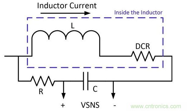
We almost always need to measure some type of current. This article will focus on lossless current sensing techniques. Use circuit components you already have! We will look at two methods of current sensing using circuit components you already have. These methods are inductor DCR sensing and FET sensing. Inductor DCR sensing is not super accurate, but it is adequate. The DCR of an inductor is usually on the order of +/- 10%. The temperature coefficient will vary due to the copper, and you may get some very inaccurate measurements. The good news is that after the DCR network, you end up with a very clean signal that is free of switching noise. Figure 1 shows the network needed to extract current information from the DCR of an inductor.  The components of this network are selected using the following formula:

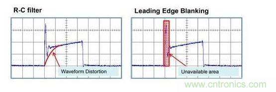
There are several factors to consider when setting up the DCR network: 1. The maximum amount of signal that the controller or sensing circuit can handle - splitting may be required. 2. Temperature compensation - components with negative temperature coefficients can be used to help keep the DCR constant as temperature changes. DCR sensing is often used in multi-phase configurations to implement circuit mode control. Current sharing between multiple phases is easy to implement using this technique. Use FET sensing, but keep an eye on switching noise! When FETs switch, a lot of noise is generated. This noise needs to be filtered. Figure 2 shows a FET sensing scheme and how noise can interfere with the measurement. There are several ways to reduce noise, but they all have drawbacks. 1. Filters using RC networks. This can be used, but it rounds the current signal, making the edges less sharp. The rounded current sense signal can cause jitter and other noise issues. 2. Leading edge blanking. This is a technique that ignores the first portion of the current sense signal. The main problem with this method is that it causes a minimum on time, and if there is a problem, the duty cycle can only be reduced so much. Figure 3 shows the drawbacks of the above two methods.
Lossless current sensing techniques are not as accurate as using precision resistors, but they avoid efficiency and power loss issues. Lossless methods are usually more suitable for applications where efficiency gains are more important than accuracy. Current sensing methods are by no means limited to the methods described in the last two blogs. Please leave a comment and let us know how you do it!
Keywords:Sensing
Reference address:How to sense two types of current losslessly to measure current? Look here!
 The components of this network are selected using the following formula:
There are several factors to consider when setting up the DCR network: 1. The maximum amount of signal that the controller or sensing circuit can handle - splitting may be required. 2. Temperature compensation - components with negative temperature coefficients can be used to help keep the DCR constant as temperature changes. DCR sensing is often used in multi-phase configurations to implement circuit mode control. Current sharing between multiple phases is easy to implement using this technique. Use FET sensing, but keep an eye on switching noise! When FETs switch, a lot of noise is generated. This noise needs to be filtered. Figure 2 shows a FET sensing scheme and how noise can interfere with the measurement. There are several ways to reduce noise, but they all have drawbacks.
 1. Filters using RC networks. This can be used, but it rounds the current signal, making the edges less sharp. The rounded current sense signal can cause jitter and other noise issues. 2. Leading edge blanking. This is a technique that ignores the first portion of the current sense signal. The main problem with this method is that it causes a minimum on time, and if there is a problem, the duty cycle can only be reduced so much. Figure 3 shows the drawbacks of the above two methods.
Lossless current sensing techniques are not as accurate as using precision resistors, but they avoid efficiency and power loss issues. Lossless methods are usually more suitable for applications where efficiency gains are more important than accuracy. Current sensing methods are by no means limited to the methods described in the last two blogs. Please leave a comment and let us know how you do it!
Previous article:Accurately measure small resistance values, zero error is not a problem
Next article:Interpretation of diode surge current test circuit
- Popular Resources
- Popular amplifiers
Recommended Content
Latest Test Measurement Articles
- Seizing the Opportunities in the Chinese Application Market: NI's Challenges and Answers
- Tektronix Launches Breakthrough Power Measurement Tools to Accelerate Innovation as Global Electrification Accelerates
- Not all oscilloscopes are created equal: Why ADCs and low noise floor matter
- Enable TekHSI high-speed interface function to accelerate the remote transmission of waveform data
- How to measure the quality of soft start thyristor
- How to use a multimeter to judge whether a soft starter is good or bad
- What are the advantages and disadvantages of non-contact temperature sensors?
- In what situations are non-contact temperature sensors widely used?
- How non-contact temperature sensors measure internal temperature
MoreSelected Circuit Diagrams
MorePopular Articles
- LED chemical incompatibility test to see which chemicals LEDs can be used with
- Application of ARM9 hardware coprocessor on WinCE embedded motherboard
- What are the key points for selecting rotor flowmeter?
- LM317 high power charger circuit
- A brief analysis of Embest's application and development of embedded medical devices
- Single-phase RC protection circuit
- stm32 PVD programmable voltage monitor
- Introduction and measurement of edge trigger and level trigger of 51 single chip microcomputer
- Improved design of Linux system software shell protection technology
- What to do if the ABB robot protection device stops
MoreDaily News
- Wi-Fi 8 specification is on the way: 2.4/5/6GHz triple-band operation
- Wi-Fi 8 specification is on the way: 2.4/5/6GHz triple-band operation
- Vietnam's chip packaging and testing business is growing, and supply-side fragmentation is splitting the market
- Vietnam's chip packaging and testing business is growing, and supply-side fragmentation is splitting the market
- Three steps to govern hybrid multicloud environments
- Three steps to govern hybrid multicloud environments
- Microchip Accelerates Real-Time Edge AI Deployment with NVIDIA Holoscan Platform
- Microchip Accelerates Real-Time Edge AI Deployment with NVIDIA Holoscan Platform
- Melexis launches ultra-low power automotive contactless micro-power switch chip
- Melexis launches ultra-low power automotive contactless micro-power switch chip
Guess you like
- The electronic competition is coming again, come and vote, will you participate?
- 【FAQ】 TPS63020: Phase margin improvement method
- KiCad requires the use of the new kicad.org domain
- 【GD32307E-START】+ Dual-color OLED screen driver display
- [Automatic clock-in walking timing system based on face recognition] Maixbit K210 serial communication protocol debugging
- CAN bus receives error information? Add CRC check in the data?
- Working principle, purpose and use of flexible waveguide
- Motor Control Basics - Timer Encoder Mode Usage and Speed Calculation
- Thank you-Chengdu
- [Xianji HPM6750 Review 7] A video player that reads RGB data files from an SD card

 TDF8546ATH/N1ZJ


 京公网安备 11010802033920号