1. Probe classification
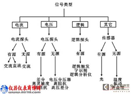
Probes are usually classified according to the measurement object, as shown in Figure 1. Among them, high-resistance passive probes, high-voltage differential probes and current probes are the most familiar to us, and a brief introduction is given below.
Figure 1 Probe classification
Figure 2 Passive probe compensation
Table 1 ZP1025S specifications and models
Figure 3 High-voltage differential probe principle
Table 2 Specifications of common high voltage differential probes
Figure 4 Current probe image
Keywords:Oscilloscope
Reference address:How to achieve the best match for oscilloscope probes?
1.11.1 High-impedance passive probes
From the perspective of actual needs, high-impedance passive voltage probes with compensation are used in the largest proportion and can meet the needs of most low-speed digital signals, power supplies and other typical oscilloscopes.
This type of probe has a higher input resistance (generally above 1MΩ) and an adjustable compensation capacitor. When connected to an oscilloscope for the first time, it is generally necessary to adjust the capacitance value with an adjustment rod to match the oscilloscope input capacitance and eliminate low-frequency or high-frequency gain. The left side of Figure 2 shows an under-compensated waveform, the middle shows a normal waveform, and the right side shows an over-compensated waveform.
For example, the ZDS2024PLUS comes standard with the ZP1025S high-impedance passive voltage probe, and its specific parameters are as follows:
1.21.2 High-voltage differential probe
First, let's introduce the concept of differential: differential signals are signals that reference each other, not the ground. The high-voltage differential probe is essentially composed of two symmetrical voltage probes, each with good insulation and high impedance to the ground. It can provide a high common-mode rejection ratio in a wider frequency range and can convert any two-point floating signals into ground signals. It is mainly used for testing industries such as switching power supplies. The schematic diagram is shown in Figure 3.
The following table shows the specific parameters of common high-voltage differential probes:

1.31.3 Current probe
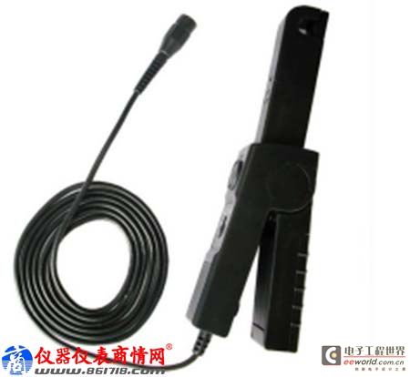
The current probe uses a Hall sensor and an induction coil to measure DC and AC currents. Its working principle is to convert the current signal into a voltage signal. The oscilloscope collects the voltage signal and then displays it as a current signal.
The advantage of the current probe is that the current can be measured without disconnecting the power supply line. Typical applications are system power measurement, power factor measurement, and switch impact current waveform measurement. The main disadvantage is that its small current measurement capability is limited by the bottom noise of the oscilloscope, so the small current measurement capability is limited.
2. How to choose a suitable probe?
The above briefly introduces some common probes. So how should we choose a suitable probe? What parameters of the probe should we pay attention to?
1. Impedance matching: The input impedance of the probe should match the input impedance of the oscilloscope used to reduce the load on the circuit under test. For oscilloscopes with low input impedance, active probes or probes with 50Ω input impedance should be selected; for oscilloscopes with high input impedance, ×10 probes should be selected. For example, if the input impedance of the oscilloscope is 1MΩ/10pF, the probe input impedance is preferably 10MΩ/1pF. Such a probe has 10 times the signal attenuation, a small load on the measured signal, and can match the input impedance of the oscilloscope.
2. Bandwidth: The bandwidth of the probe should be equal to or greater than the bandwidth of the oscilloscope. If a pure sinusoidal signal is observed, the probe bandwidth can be equal to the highest value of the measured signal frequency; if a non-sinusoidal signal is observed, the probe bandwidth should accommodate the fundamental wave and the most important harmonic components of the measured signal.
3. Rise time: In order to accurately measure the rise time and fall time of the pulse, the rise time of the system (that is, the sum of the oscilloscope and probe rise time) should be 3-5 times faster than the rise time of the measured signal.
3. Summary
To ensure the accuracy of the test results, the probe is required to have minimal impact on the circuit under test and maintain the maximum signal fidelity transmitted to the oscilloscope. If the probe changes the signal or the operation mode of the circuit under test in any way, the oscilloscope will see the distortion of the actual signal, which may lead to incorrect measurement results, or misleading measurement results. Only probes that are well matched to both the oscilloscope and the circuit under test are your best choice!
Previous article:Effect of Frequency on Electrical Measurement Accuracy
Next article:What is the difference between a voltmeter and an oscilloscope?
- Popular Resources
- Popular amplifiers
Recommended Content
Latest Test Measurement Articles
- Seizing the Opportunities in the Chinese Application Market: NI's Challenges and Answers
- Tektronix Launches Breakthrough Power Measurement Tools to Accelerate Innovation as Global Electrification Accelerates
- Not all oscilloscopes are created equal: Why ADCs and low noise floor matter
- Enable TekHSI high-speed interface function to accelerate the remote transmission of waveform data
- How to measure the quality of soft start thyristor
- How to use a multimeter to judge whether a soft starter is good or bad
- What are the advantages and disadvantages of non-contact temperature sensors?
- In what situations are non-contact temperature sensors widely used?
- How non-contact temperature sensors measure internal temperature
MoreSelected Circuit Diagrams
MorePopular Articles
- LED chemical incompatibility test to see which chemicals LEDs can be used with
- Application of ARM9 hardware coprocessor on WinCE embedded motherboard
- What are the key points for selecting rotor flowmeter?
- LM317 high power charger circuit
- A brief analysis of Embest's application and development of embedded medical devices
- Single-phase RC protection circuit
- stm32 PVD programmable voltage monitor
- Introduction and measurement of edge trigger and level trigger of 51 single chip microcomputer
- Improved design of Linux system software shell protection technology
- What to do if the ABB robot protection device stops
MoreDaily News
- Detailed explanation of intelligent car body perception system
- How to solve the problem that the servo drive is not enabled
- Why does the servo drive not power on?
- What point should I connect to when the servo is turned on?
- How to turn on the internal enable of Panasonic servo drive?
- What is the rigidity setting of Panasonic servo drive?
- How to change the inertia ratio of Panasonic servo drive
- What is the inertia ratio of the servo motor?
- Is it better for the motor to have a large or small moment of inertia?
- What is the difference between low inertia and high inertia of servo motors?
Guess you like
- [RVB2601 Creative Application Development] Configure serial port 1 UART1 echo
- Introduction to TMS320C25's memory allocation and other hardware
- Calculate the reasonable setting of mesh ratio
- After copper plating, DRC reports an error
- ①、Development board received
- Industry 4.0 will become the dominant application of IoT within 5 years, what do you think???
- EEWORLD University - Inverter Principle
- Bluetooth and MSP430 Audio Sink Reference Design
- Apprentice
- 【ST NUCLEO-G071RB Review】TIM-Basic timers