Current measurement technology has a wide range of applications, and many systems need to detect the magnitude of the inflow and outflow current. For example, current protection/current monitoring equipment, 4-20mA current loop systems, programmable current sources, linear/switch mode power supplies, and chargers or battery fuel gauges that need to know the ratio of inflow and outflow current. Since many applications are portable, the current sensing circuit must also have the characteristics of small size and low power consumption.
High-side/low-side current sensing circuit The
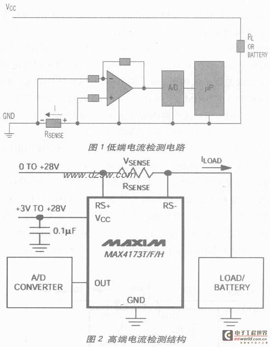
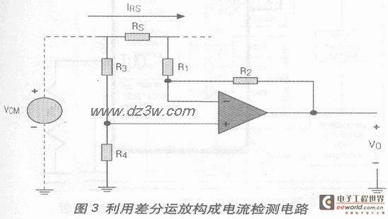
current sensing resistor of the low-side current sensing circuit is connected in series to the ground (Figure 1), while the current sensing resistor of the high-side current sensing circuit is connected in series to the high voltage terminal (Figure 2). Both methods have their own characteristics: the low-side current sensing method adds additional resistance in the ground loop, and the high-side current sensing method has to deal with larger common-mode signals. The
low-side current sensing op amp shown in Figure 1 uses the ground level as the reference level, and the current sensing resistor is connected to the non-inverting terminal.
The common-mode signal range in the input signal of the op amp is: (GNDRSENSE*ILOAD). Although the low-end current sensing circuit is relatively simple, there are several fault conditions that the low-end current sensing circuit cannot detect, which will put the load in a dangerous situation. The high-end current sensing circuit can solve these problems.
The high-end current sensing circuit is directly connected to the power supply terminal and can detect any faults in the subsequent circuit and take corresponding protection measures. It is particularly suitable for automatic control applications because the chassis is usually used as the reference ground in these application circuits.
Traditional high-end current sensing circuit
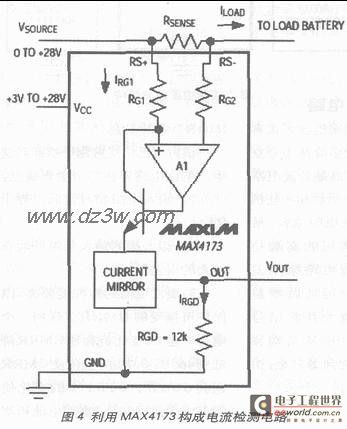
There are many implementation schemes for traditional high-end/low-end current sensing, most of which are based on discrete or semi-discrete component circuits. The high-end current sensing circuit usually requires a precision op amp and some precision resistors and capacitors. The most commonly used high-end current sensing circuit uses a differential op amp for gain amplification and shifts the signal level from the high side to the reference ground (Figure 3): VO=IRS*RS; R1=R2=R3=R4 This scheme has been widely used in actual systems, but this circuit has three major disadvantages:
1) The input resistance is relatively low, equal to R1;
2) The input resistance at the input terminal generally has a large error value;
3) The resistor matching degree is required to ensure acceptable CMRR. A 1% change in any resistor reduces the CMRR to 46dB; a 0.1% change increases the CMRR to 66dB, and a 0.01% change increases the CMRR to 86dB. The high-side current sensing requires a high level of measurement skill, which has led to the development of high-side current sensing integrated circuits. Low-side current sensing technology does not seem to have made the same progress.
High-side Current Sensing with Integrated Differential Op Amps
Circuits that use differential op amps for high-side current sensing are more user-friendly because many integrated circuit solutions have been introduced recently. The integrated circuits contain a precision op amp and well-matched resistors, and the CMRR is as high as 105dB. The MAX4198/99 is such a product, with a CMRR of 110dB, a gain error of better than 0.01%, and a small 8-pin MMAX package.
Dedicated high-side current sensing circuits contain all the functional units to complete high-side current sensing, can sense high-side current at common-mode voltages up to 32V, and provide a proportional, ground-referenced current output. Applications that require accurate measurement and control of current, such as power management and battery charging control, are suitable for this solution. The
current sensing resistor used in MAXIM's high-end current sensing op amp is placed between the high-end of the power supply and the power input of the circuit being detected. Placing the current sensing resistor at the high end does not add additional impedance to the ground loop. This technology improves the performance of the entire circuit and simplifies the layout requirements.
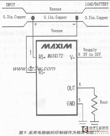
MAXIM has launched a series of bidirectional or unidirectional current sensing ICs. Some bidirectional current sensing ICs have built-in current sensing resistors that can detect the current flowing into or out of the circuit being detected and display the current direction through a polarity indication pin. Gain-adjustable current sensing ICs, fixed gain (+20V/V, +50V/V, or +100V/V) current sensing chips, or fixed gain current sensing ICs including single and dual comparators all use small packages, such as SOT23, to meet applications with demanding size requirements. Figure 4 shows a high-end current sensing circuit constructed using MAX4173.
The relationship between the output voltage and the current-sense resistor in the figure is:
Vo=RGD*(Iload*Rsense)/RG1)*B, where B is the mirror current coefficient. The
above formula can be further simplified to:
Vo=Gain*Rsense*Iload; Gain= B*RGD/RG1. Gain is:
20 (MAX4173T), 50 (MAX4173F), 100 (MAX4173H).
It can be seen from the above calculation formula that CMRR is determined by the process of the internal integrated current-sense circuit (typical value>90dB) and is no longer affected by external resistance.
The use of integrated current-sense circuit has the following advantages:
1. Good consistency of devices
2. Excellent temperature drift characteristics
3. Small size
4. Low power consumption
5. Easy to use. Precautions for selecting current-sense resistors.
The current-sense resistor RSENSE should be selected according to the following principles:
1. Voltage loss: If the resistance of the current-sense resistor is too large, the power supply voltage will be reduced by the value of IR. In order to reduce voltage loss, a small resistance current-sense resistor should be selected.
2. Accuracy: A larger current-sense resistor can achieve higher accuracy for measuring small currents. This is because the larger the voltage on the current-sense resistor, the smaller the impact of the op amp's offset voltage and input bias current.
3. Efficiency and power consumption: When the current is large, the power consumption I2R on RSENSE cannot be ignored. This needs to be kept in mind when considering the current-sense resistor and power consumption. If the current-sense resistor is allowed to heat up, the resistance value can be larger.
4. Inductance: If ISENSE contains a lot of high-frequency components, the inductance of the current-sense resistor should be very small. Wirewound resistors have the largest inductance, and metal film resistors are better.
5. Cost: If the price of a suitable current-sense resistor is too high, another alternative can be used (Figure 5). It uses the printed circuit board's printed wire as the current-sense resistor. Because the "resistance" of the printed circuit board copper wire is not accurate, a potentiometer is required in the circuit to adjust the full-scale current value. In addition, the temperature drift of the copper wire is large (about 0.4%/℃), which needs to be considered in systems operating over a wide temperature range.
Adjustable linear current source
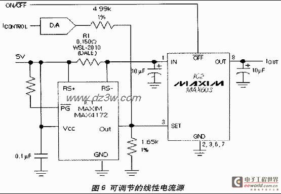
The adjustable linear current source (Figure 6) is a typical application circuit composed of a high-end current detector. IC1 converts the current of R1 into a proportional voltage signal, controls the voltage regulator chip IC2 to produce a stable output current, and the D/A converter can provide digital control of IOUT. To achieve the requirement of 12 BIT accuracy (60mA per LSB), the MAX530 with parallel interface or the MAX531 with serial interface can be used. For 10 BIT accuracy (250mA per LSB), the MAX503 with parallel interface or the MAX504 with serial interface can be used.
Keywords:MAX4172 MAX4173
Reference address:MAX4172/MAX4173 High-Side Current Detection Circuit Principle and Design
High-side/low-side current sensing circuit The
current sensing resistor of the low-side current sensing circuit is connected in series to the ground (Figure 1), while the current sensing resistor of the high-side current sensing circuit is connected in series to the high voltage terminal (Figure 2). Both methods have their own characteristics: the low-side current sensing method adds additional resistance in the ground loop, and the high-side current sensing method has to deal with larger common-mode signals. The
low-side current sensing op amp shown in Figure 1 uses the ground level as the reference level, and the current sensing resistor is connected to the non-inverting terminal.
The common-mode signal range in the input signal of the op amp is: (GNDRSENSE*ILOAD). Although the low-end current sensing circuit is relatively simple, there are several fault conditions that the low-end current sensing circuit cannot detect, which will put the load in a dangerous situation. The high-end current sensing circuit can solve these problems.
The high-end current sensing circuit is directly connected to the power supply terminal and can detect any faults in the subsequent circuit and take corresponding protection measures. It is particularly suitable for automatic control applications because the chassis is usually used as the reference ground in these application circuits.

Traditional high-end current sensing circuit
There are many implementation schemes for traditional high-end/low-end current sensing, most of which are based on discrete or semi-discrete component circuits. The high-end current sensing circuit usually requires a precision op amp and some precision resistors and capacitors. The most commonly used high-end current sensing circuit uses a differential op amp for gain amplification and shifts the signal level from the high side to the reference ground (Figure 3): VO=IRS*RS; R1=R2=R3=R4 This scheme has been widely used in actual systems, but this circuit has three major disadvantages:
1) The input resistance is relatively low, equal to R1;
2) The input resistance at the input terminal generally has a large error value;
3) The resistor matching degree is required to ensure acceptable CMRR. A 1% change in any resistor reduces the CMRR to 46dB; a 0.1% change increases the CMRR to 66dB, and a 0.01% change increases the CMRR to 86dB. The high-side current sensing requires a high level of measurement skill, which has led to the development of high-side current sensing integrated circuits. Low-side current sensing technology does not seem to have made the same progress.

High-side Current Sensing with Integrated Differential Op Amps
Circuits that use differential op amps for high-side current sensing are more user-friendly because many integrated circuit solutions have been introduced recently. The integrated circuits contain a precision op amp and well-matched resistors, and the CMRR is as high as 105dB. The MAX4198/99 is such a product, with a CMRR of 110dB, a gain error of better than 0.01%, and a small 8-pin MMAX package.
Dedicated high-side current sensing circuits contain all the functional units to complete high-side current sensing, can sense high-side current at common-mode voltages up to 32V, and provide a proportional, ground-referenced current output. Applications that require accurate measurement and control of current, such as power management and battery charging control, are suitable for this solution. The
current sensing resistor used in MAXIM's high-end current sensing op amp is placed between the high-end of the power supply and the power input of the circuit being detected. Placing the current sensing resistor at the high end does not add additional impedance to the ground loop. This technology improves the performance of the entire circuit and simplifies the layout requirements.
MAXIM has launched a series of bidirectional or unidirectional current sensing ICs. Some bidirectional current sensing ICs have built-in current sensing resistors that can detect the current flowing into or out of the circuit being detected and display the current direction through a polarity indication pin. Gain-adjustable current sensing ICs, fixed gain (+20V/V, +50V/V, or +100V/V) current sensing chips, or fixed gain current sensing ICs including single and dual comparators all use small packages, such as SOT23, to meet applications with demanding size requirements. Figure 4 shows a high-end current sensing circuit constructed using MAX4173.

The relationship between the output voltage and the current-sense resistor in the figure is:
Vo=RGD*(Iload*Rsense)/RG1)*B, where B is the mirror current coefficient. The
above formula can be further simplified to:
Vo=Gain*Rsense*Iload; Gain= B*RGD/RG1. Gain is:
20 (MAX4173T), 50 (MAX4173F), 100 (MAX4173H).
It can be seen from the above calculation formula that CMRR is determined by the process of the internal integrated current-sense circuit (typical value>90dB) and is no longer affected by external resistance.
The use of integrated current-sense circuit has the following advantages:
1. Good consistency of devices
2. Excellent temperature drift characteristics
3. Small size
4. Low power consumption
5. Easy to use. Precautions for selecting current-sense resistors.
The current-sense resistor RSENSE should be selected according to the following principles:
1. Voltage loss: If the resistance of the current-sense resistor is too large, the power supply voltage will be reduced by the value of IR. In order to reduce voltage loss, a small resistance current-sense resistor should be selected.
2. Accuracy: A larger current-sense resistor can achieve higher accuracy for measuring small currents. This is because the larger the voltage on the current-sense resistor, the smaller the impact of the op amp's offset voltage and input bias current.
3. Efficiency and power consumption: When the current is large, the power consumption I2R on RSENSE cannot be ignored. This needs to be kept in mind when considering the current-sense resistor and power consumption. If the current-sense resistor is allowed to heat up, the resistance value can be larger.
4. Inductance: If ISENSE contains a lot of high-frequency components, the inductance of the current-sense resistor should be very small. Wirewound resistors have the largest inductance, and metal film resistors are better.
5. Cost: If the price of a suitable current-sense resistor is too high, another alternative can be used (Figure 5). It uses the printed circuit board's printed wire as the current-sense resistor. Because the "resistance" of the printed circuit board copper wire is not accurate, a potentiometer is required in the circuit to adjust the full-scale current value. In addition, the temperature drift of the copper wire is large (about 0.4%/℃), which needs to be considered in systems operating over a wide temperature range.

Adjustable linear current source
The adjustable linear current source (Figure 6) is a typical application circuit composed of a high-end current detector. IC1 converts the current of R1 into a proportional voltage signal, controls the voltage regulator chip IC2 to produce a stable output current, and the D/A converter can provide digital control of IOUT. To achieve the requirement of 12 BIT accuracy (60mA per LSB), the MAX530 with parallel interface or the MAX531 with serial interface can be used. For 10 BIT accuracy (250mA per LSB), the MAX503 with parallel interface or the MAX504 with serial interface can be used.

Previous article:Power module limit test method
Next article:Design of temperature measurement system of platinum resistance
- Popular Resources
- Popular amplifiers
Recommended Content
Latest Test Measurement Articles
- New IsoVu™ Isolated Current Probes: Bringing a New Dimension to Current Measurements
- Modern manufacturing strategies drive continuous improvement in ICT online testing
- Methods for Correlation of Contact and Non-Contact Measurements
- Keysight Technologies Helps Samsung Electronics Successfully Validate FiRa® 2.0 Safe Distance Measurement Test Case
- From probes to power supplies, Tektronix is leading the way in comprehensive innovation in power electronics testing
- Seizing the Opportunities in the Chinese Application Market: NI's Challenges and Answers
- Tektronix Launches Breakthrough Power Measurement Tools to Accelerate Innovation as Global Electrification Accelerates
- Not all oscilloscopes are created equal: Why ADCs and low noise floor matter
- Enable TekHSI high-speed interface function to accelerate the remote transmission of waveform data
MoreSelected Circuit Diagrams
MorePopular Articles
- Intel promotes AI with multi-dimensional efforts in technology, application, and ecology
- ChinaJoy Qualcomm Snapdragon Theme Pavilion takes you to experience the new changes in digital entertainment in the 5G era
- Infineon's latest generation IGBT technology platform enables precise control of speed and position
- Two test methods for LED lighting life
- Don't Let Lightning Induced Surges Scare You
- Application of brushless motor controller ML4425/4426
- Easy identification of LED power supply quality
- World's first integrated photovoltaic solar system completed in Israel
- Sliding window mean filter for avr microcontroller AD conversion
- What does call mean in the detailed explanation of ABB robot programming instructions?
MoreDaily News
- STMicroelectronics discloses its 2027-2028 financial model and path to achieve its 2030 goals
- 2024 China Automotive Charging and Battery Swapping Ecosystem Conference held in Taiyuan
- State-owned enterprises team up to invest in solid-state battery giant
- The evolution of electronic and electrical architecture is accelerating
- The first! National Automotive Chip Quality Inspection Center established
- BYD releases self-developed automotive chip using 4nm process, with a running score of up to 1.15 million
- GEODNET launches GEO-PULSE, a car GPS navigation device
- Should Chinese car companies develop their own high-computing chips?
- Infineon and Siemens combine embedded automotive software platform with microcontrollers to provide the necessary functions for next-generation SDVs
- Continental launches invisible biometric sensor display to monitor passengers' vital signs
Guess you like
- TI high-side and low-side drivers 4A peak current 120V boost solution
- What do you want to do after the national competition?
- I haven't posted for a long time.
- Waveform recognition software production guide
- What you should know about RF power amplifiers
- Design considerations for electric vehicle charger circuit topology1
- TI C6000 Optimization Manual - Make Code Look Like Nails
- Will the voltage of LM358 continue to decrease during actual use?
- Last day! Prize live broadcast: ST's new generation of low-power Bluetooth protocol stack: highly flexible, easy to use, and customizable!
- Using AT89C2051 compatible chip to make six-digit display multi-channel timing electronic clock

 TC1039NECHRT


 京公网安备 11010802033920号