Most oscilloscopes offer an auxiliary trigger system or "B" trigger that allows the user to define a wider range of conditions. The B trigger waits for the primary (or "primary") trigger to occur, and then triggers the acquisition when its own edge threshold is crossed. The two can be used in conjunction to set up some fairly complex trigger conditions. For example, A may detect a glitch on the device clock input line, and B can be triggered if a rising or falling edge is encountered on the output. If there is no such transition, the glitch can be ignored. The two sets of conditions are used in conjunction to determine whether the glitch will cause an unwanted state change.
Until recently, B-trigger functionality has been limited to edge detection. However, complex new signal formats, especially those used in serial protocols such as PCI Express and Serial ATA, require a better match between the capabilities of the trigger system and the signals it is processing.
Errors in these fast new protocols can come from the combined results of multiple events, such as logic states, offsets, transients, rise time issues, etc. Sometimes, a very precise range of conditions must be specified to identify elusive errors. This requires a trigger tool set that can analyze more conditions. This problem can be solved using a dual trigger arrangement, in which the B trigger system is basically the same as the A system. It's just that in many cases, the A conditions are relatively simple, and ideally, the B trigger should be able to evaluate a more complex set of indicators, such as the number of events that are only valid when other logic signals are in a specified state. However, the correlation trigger B has always lacked the flexibility of the A trigger system. Therefore, most oscilloscopes only provide a very simple B trigger.
Let the two triggers run together
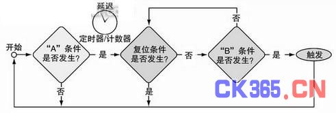
Figure 1 shows a fully functional dual trigger system in simplified form.

Figure 1 Full-function dual-trigger structure
The trigger at the end will help the oscilloscope capture problematic signals. The conditions that may occur are as follows:
Whether event A has occurred. Users can specify edge, clipped pulse or many other conditions;
Whether the correct logic state (collected from at most two different inputs) is in effect when event A occurs;
Whether the delay condition between trigger A and trigger B is met. "Delay" can be expressed in terms of time or number of events;
Whether a B event occurred. This can be a setup/hold violation, a clipped pulse, or any selection from the same list of types used for the A trigger;
Whether the correct logic state (also collected from up to two different inputs) is in effect when event B occurs;
If a reset condition occurs at any point in the process, the reset will bypass all subsequent steps and return to the beginning.
The flexibility of the trigger system is significantly improved by executing the above conditions in sequence. When considering these two event conditions and logical determinants at the same time, the number of possible combinations can reach thousands. In this way, the user has a range of programming options, from simple edge thresholds on a single input to complex formulas using two triggers, logical determinations, and time or number of events.
IF-THEN-ELSE, which comes from the field of computer programming, constitutes the conceptual model of this type of trigger structure. As shown in Figure 1, these statements also include other predicates (such as timers/counters between A and B). Regardless of whether the B event occurs, a reset can occur at any time after the A event.
Using two flip-flops to find a pulse
This article introduces a fully symmetrical dual-trigger system through a recent disk drive design project.
In this system, a unit in the read/write circuit is designed to execute a series of 32 write commands in each valid system write enable (WE) cycle. Figure 2 describes the relationship between the larger cycle time and the individual pulses that cause data to be written.

Figure 2 Two flip-flops capture a deviated write pulse
In this emerging design, intermittent errors are caused by extra pulses occurring in certain cycles. Although there is no way to guess when the 33rd pulse will occur, having a way to capture the sequence of different 33 pulses makes it easier to identify other system events that may be related.
One solution is to use a traditional edge trigger to acquire multiple repeated WE cycles and the associated write pulse sequence, detect the leading edge of each WE cycle, and then manually scroll through the data to find the problematic cycle. This method is time-consuming and cannot guarantee that the erroneous pulse will only appear once within the storage capacity of the oscilloscope waveform. The solution that engineers prefer is to trigger the acquisition only when 33 pulse cycles occur. The advantage is that the cycle of interest will automatically appear on the screen without the troublesome manual search. Of course, the relevant data before and after the trigger event will be stored, but the simple fact that the trigger occurred confirms the existence of 33 pulse cycles.
This is where a dual trigger system comes in. In this case, the disk drive designer needs to set up a related trigger where the leading edge (positive going edge) of the WE signal acts as the A trigger event and the trailing edge acts as the reset condition.
In this process, the A event starts the delay counter to count the number of pulses. Once 32 pulses are generated, it causes the B trigger to monitor the 33rd pulse. When a specific pulse width is detected, the B system is set to trigger acquisition, at which point the oscilloscope triggers and records the data. If there is no 33rd pulse, the reset condition re-arms the A trigger and starts the whole process again.
This approach would not be possible if the B trigger was limited to edge detection. In this process, the reset function value should not be overlooked, because it determines that if the corresponding combination of A and B events does not occur, the oscilloscope and its user will not wait forever.
The abnormal 33rd pulse is the result of a logic design error elsewhere in the circuit. Thanks to the reliable deviation pulse detection method, designers can use logical judgment to further narrow down the trigger conditions and find the fault. [page]
Detecting channel skew
Many serial communication technologies started out as single-channel serial transmission structures, and later evolved to add multiple synchronous transmission paths to provide higher data rates. These paths are not synchronized in the way of parallel buses, because the data will be realigned in the destination device. However, there is a limit to the delay or offset allowed between related data packets transmitted over the serial link, and failure to comply with this limit is called "path overrun".
In its most basic form, the overrun measurement consists of triggering a character on one of the data streams and the relative data skew in the adjacent lane. But the skew can vary over time, and a lane that is within tolerance at one point in time may cross the boundary at another, so it is the skew behavior over the long term that is critical.
The oscilloscope with full-featured dual trigger system provides a powerful tool for monitoring offset changes. It can detect the time offset between any two channels at any time, which can be a few ns or a few days. It can also capture events that exceed the offset time range on the display and count the number of events using the instrument's acquisition counter.

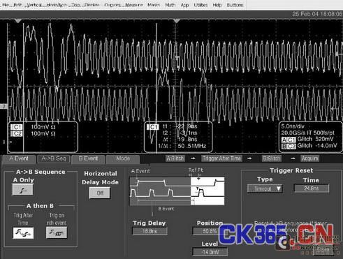
Figure 3 Serial channel skew overrun measurement
Figure 3 is an example of pass/fail testing of offset measurements that fall anywhere within the 8 ns time window. The setup is as follows:
The A event is a comma character on lane 0. Since it has a guessable pulse width, the comma can be detected using the pulse width trigger format.
The B event is the comma character in channel 1, which is captured by defining a pulse width trigger in the B system.
The programmed delay between the A and B flip-flops is set to 16.8 ns, which is the specification of the device under test and the “early” edge of the window.
The reset time value is set to 24.8 ns, which is the tolerance allowed by the bus standard and is the other boundary of the window.
In this case, if an A event is detected, the B trigger will fire if the event skew for channel 1 falls between 16.8 ns and 24.8 ns. If no B event is detected before the 24.8 ns limit expires, the instrument will re-arm the A trigger and begin looking for a new cycle. In Figure 3, the acquisition shows that the skew between the two channels is 19.8 ns.
Monitoring beacons
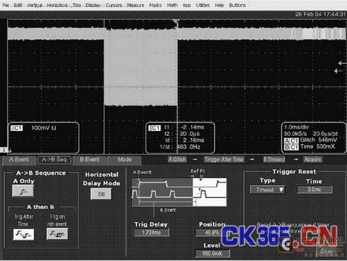
Many serial communications devices indicate their presence on a communications channel by transmitting a "beacon" signal consisting of a header and a variable-length data block of a special packet. Sometimes these devices power up in an error state and transmit a beacon that contains additional information about the device's status, which can cause the beacon to be longer than normal. The maximum length of the beacon signal is part of the specification for most devices, so any over-limit characteristics must be checked. An oscilloscope with a full-featured A trigger system and B trigger system can solve this measurement problem. Figure 4 is a screen shot of the acquisition settings when a beacon width over-limit is detected.

Figure 4 Detection of beacon width exceeding the limit
The A event trigger is set to detect the comma character in the beacon signal header packet (K28.5, 8b/10b format). To do this, a pulse width trigger format is used. A valid A event is defined as the total pulse width consisting of five binary 1s or 0s in the comma character.
Set the delay time of AB on the maximum width of a "correct" beacon signal. The B flip-flop does not start evaluating its condition until the delay has expired, at which point the beacon should be idle.
The B event trigger is set to time out. In the language of trigger systems, this is defined as a period of time when no transitions occur, in other words, no signal. If beacon activity is detected when it should be "nothing", the B trigger will be triggered.
The reset condition is also expressed in time. It defines the end time when measuring the cycle of interest. It is set to 3.0 ms, and its main function is to prepare the A trigger for another acquisition.
Under the trigger conditions summarized above, the oscilloscope will easily detect the beacon width error, revealing the problem in the design.
Conclusion
The above application examples rely on two robust symmetrical trigger systems working in parallel. These examples illustrate how the complex correlations of signals and errors generated in today's fast digital devices can be observed with a flexible two-stage trigger system. Modern digital oscilloscopes with symmetrical A and B triggers provide an ideal means to meet these and other difficult measurement challenges.
Previous article:What should you pay attention to when choosing an oscilloscope?
Next article:How to distinguish between analog bandwidth and digital real-time bandwidth of oscilloscope
- Keysight Technologies Helps Samsung Electronics Successfully Validate FiRa® 2.0 Safe Distance Measurement Test Case
- From probes to power supplies, Tektronix is leading the way in comprehensive innovation in power electronics testing
- Seizing the Opportunities in the Chinese Application Market: NI's Challenges and Answers
- Tektronix Launches Breakthrough Power Measurement Tools to Accelerate Innovation as Global Electrification Accelerates
- Not all oscilloscopes are created equal: Why ADCs and low noise floor matter
- Enable TekHSI high-speed interface function to accelerate the remote transmission of waveform data
- How to measure the quality of soft start thyristor
- How to use a multimeter to judge whether a soft starter is good or bad
- What are the advantages and disadvantages of non-contact temperature sensors?
- Innolux's intelligent steer-by-wire solution makes cars smarter and safer
- 8051 MCU - Parity Check
- How to efficiently balance the sensitivity of tactile sensing interfaces
- What should I do if the servo motor shakes? What causes the servo motor to shake quickly?
- 【Brushless Motor】Analysis of three-phase BLDC motor and sharing of two popular development boards
- Midea Industrial Technology's subsidiaries Clou Electronics and Hekang New Energy jointly appeared at the Munich Battery Energy Storage Exhibition and Solar Energy Exhibition
- Guoxin Sichen | Application of ferroelectric memory PB85RS2MC in power battery management, with a capacity of 2M
- Analysis of common faults of frequency converter
- In a head-on competition with Qualcomm, what kind of cockpit products has Intel come up with?
- Dalian Rongke's all-vanadium liquid flow battery energy storage equipment industrialization project has entered the sprint stage before production
- Allegro MicroSystems Introduces Advanced Magnetic and Inductive Position Sensing Solutions at Electronica 2024
- Car key in the left hand, liveness detection radar in the right hand, UWB is imperative for cars!
- After a decade of rapid development, domestic CIS has entered the market
- Aegis Dagger Battery + Thor EM-i Super Hybrid, Geely New Energy has thrown out two "king bombs"
- A brief discussion on functional safety - fault, error, and failure
- In the smart car 2.0 cycle, these core industry chains are facing major opportunities!
- Rambus Launches Industry's First HBM 4 Controller IP: What Are the Technical Details Behind It?
- The United States and Japan are developing new batteries. CATL faces challenges? How should China's new energy battery industry respond?
- Murata launches high-precision 6-axis inertial sensor for automobiles
- Ford patents pre-charge alarm to help save costs and respond to emergencies
- Vote and read public opinion: Which 15th Anniversary DIY Electronic Toolbox should you choose?
- RFID (Radio Frequency Identification) Application Architecture Planning Guide
- Multiplexer Problem
- Make a Raspberry Pi "Mask Detector"
- CC2541 closing serial port problem
- Are RF engineers becoming more and more popular?
- How to solve the strange phenomenon of CCS
- CC2541 serial port 1 position 1 problem? ? ? ?
- How to analyze and design active filters---Thank you very much! ! !
- [Zhongke Bluexun AB32VG1 RISC-V board "encountered" RTT evaluation] Question post: The problem of hardware timer not being found

 Machine Vision Algorithms and Applications 2nd Edition
 Application of static fields


 京公网安备 11010802033920号