There are many occasions when it is necessary to measure the temperature of a laser, transistor, or printed circuit board with considerable accuracy. Thermistors are often chosen as temperature sensors because they are inexpensive. However, the nonlinear resistance characteristics of thermistors complicate accurate temperature conversion.
To minimize this difficulty, thermistors are often placed in a resistor divider to linearize their resistance characteristics. The linearized response is easier to convert to temperature than the thermistor's original response. To achieve the best level of linearization, two formulas are derived that help determine component values (RS and RP) for this commonly used linearization circuit.
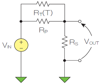
Figure 1 shows a thermistor linearization circuit. The temperature of the thermistor is (approximately) linear with the output voltage.

Figure 1: Dual-resistor thermistor linearization circuit.
First, a value for the inflection temperature TI is chosen, at which we want to obtain the smoothest possible transfer function (VOUT/VIN). The design task is to calculate the values of RS and RP given TI and its resistance ratio μ = VOUT/VIN.
The three parameters R0, β, and Tref are commonly used in equation (1) to determine the resistance value and temperature characteristics of the thermistor.

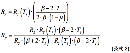
The values of RS and RP are determined by setting the second derivative of VOUT/VIN at TI in Figure 1 to zero. After much algebra, the two formulas in equation (2) are derived.

Not all ratios are possible for passive components—ratios below 1/2

will result in negative RP values.
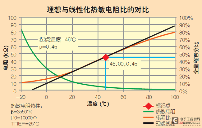
Figure 2 shows a linearized thermistor voltage transfer function plot for a common thermistor.

Figure 2: Linearized thermistor transfer function plot.
Reference address:Linearization of thermistors using a new formula
To minimize this difficulty, thermistors are often placed in a resistor divider to linearize their resistance characteristics. The linearized response is easier to convert to temperature than the thermistor's original response. To achieve the best level of linearization, two formulas are derived that help determine component values (RS and RP) for this commonly used linearization circuit.
Figure 1 shows a thermistor linearization circuit. The temperature of the thermistor is (approximately) linear with the output voltage.

Figure 1: Dual-resistor thermistor linearization circuit.
First, a value for the inflection temperature TI is chosen, at which we want to obtain the smoothest possible transfer function (VOUT/VIN). The design task is to calculate the values of RS and RP given TI and its resistance ratio μ = VOUT/VIN.
The three parameters R0, β, and Tref are commonly used in equation (1) to determine the resistance value and temperature characteristics of the thermistor.

The values of RS and RP are determined by setting the second derivative of VOUT/VIN at TI in Figure 1 to zero. After much algebra, the two formulas in equation (2) are derived.

Not all ratios are possible for passive components—ratios below 1/2

will result in negative RP values.
Figure 2 shows a linearized thermistor voltage transfer function plot for a common thermistor.

Figure 2: Linearized thermistor transfer function plot.
Previous article:Voltage monitoring devices perform multiple functions
Next article:Reduce the risk of implementing scientific computing algorithms
Recommended Content
Latest Test Measurement Articles
- Keysight Technologies Helps Samsung Electronics Successfully Validate FiRa® 2.0 Safe Distance Measurement Test Case
- From probes to power supplies, Tektronix is leading the way in comprehensive innovation in power electronics testing
- Seizing the Opportunities in the Chinese Application Market: NI's Challenges and Answers
- Tektronix Launches Breakthrough Power Measurement Tools to Accelerate Innovation as Global Electrification Accelerates
- Not all oscilloscopes are created equal: Why ADCs and low noise floor matter
- Enable TekHSI high-speed interface function to accelerate the remote transmission of waveform data
- How to measure the quality of soft start thyristor
- How to use a multimeter to judge whether a soft starter is good or bad
- What are the advantages and disadvantages of non-contact temperature sensors?
MoreSelected Circuit Diagrams
MorePopular Articles
- Innolux's intelligent steer-by-wire solution makes cars smarter and safer
- 8051 MCU - Parity Check
- How to efficiently balance the sensitivity of tactile sensing interfaces
- What should I do if the servo motor shakes? What causes the servo motor to shake quickly?
- 【Brushless Motor】Analysis of three-phase BLDC motor and sharing of two popular development boards
- Midea Industrial Technology's subsidiaries Clou Electronics and Hekang New Energy jointly appeared at the Munich Battery Energy Storage Exhibition and Solar Energy Exhibition
- Guoxin Sichen | Application of ferroelectric memory PB85RS2MC in power battery management, with a capacity of 2M
- Analysis of common faults of frequency converter
- In a head-on competition with Qualcomm, what kind of cockpit products has Intel come up with?
- Dalian Rongke's all-vanadium liquid flow battery energy storage equipment industrialization project has entered the sprint stage before production
MoreDaily News
- Allegro MicroSystems Introduces Advanced Magnetic and Inductive Position Sensing Solutions at Electronica 2024
- Car key in the left hand, liveness detection radar in the right hand, UWB is imperative for cars!
- After a decade of rapid development, domestic CIS has entered the market
- Aegis Dagger Battery + Thor EM-i Super Hybrid, Geely New Energy has thrown out two "king bombs"
- A brief discussion on functional safety - fault, error, and failure
- In the smart car 2.0 cycle, these core industry chains are facing major opportunities!
- Rambus Launches Industry's First HBM 4 Controller IP: What Are the Technical Details Behind It?
- The United States and Japan are developing new batteries. CATL faces challenges? How should China's new energy battery industry respond?
- Murata launches high-precision 6-axis inertial sensor for automobiles
- Ford patents pre-charge alarm to help save costs and respond to emergencies
Guess you like
- What challenges do IoT smart home network and device manufacturers face?
- I am looking for learning materials for analog IC power management (PMU), I am a beginner
- How to design a triode amplifier circuit
- [RISC-V MCU CH32V103 Evaluation] IIC Hardware Test (Part 2)
- C5517 FFT hardware accelerator performs calculations sometimes well and sometimes poorly
- Burn dtb file separately
- Talk about the future applications of drones and get points for speaking up
- How does a newbie learn about microcontrollers?
- How to find the power switch loop
- Award-winning live broadcast | TE interprets the design trends of smart antennas and sensor application cases in the Internet of Things

 Multisim Circuit System Design and Simulation Tutorial
 開關電源專業英語


 京公网安备 11010802033920号