Clarify the detection tasks
We must first understand how surface defects are generated and clearly classify the shapes these defects may appear in the image. For example, powder metal parts will have cracks during sintering when the material is relatively thin. Based on empirical knowledge, we can focus machine vision inspection on the area where defects occur and clearly define the inspection direction, which helps improve the reliability of defect detection.
How is the current manual inspection operation carried out? What are the shortcomings of the existing inspection system? What about accuracy, speed, full inspection or random inspection, and reliability? If machine vision replaces manual inspection, what are the requirements? This must be clearly understood in advance.
In the process of manual inspection, we can use intuition and experience to predict the possible shape of defects. For example, scratches are usually a series of straight or slightly curved line segments, and people tend to subconsciously connect these line segments into a line by relying on the "gestalt" ability in psychology. In machine vision inspection, this "gestalt" ability can be roughly manifested through visual calculation.
When performing difficult inspections, inspectors may disagree - is it a scratch? Or just a bright spot that happens to form a line? This shows that the reliability of defect detection needs to be considered. If the surface defect is clear and the defect composition is clear, the consistency and reliability of the machine vision inspection results are higher than those of manual visual inspection.
Lighting is an extremely important factor in product surface defect detection, because surface defects usually have low contrast characteristics, and they can be separated from the background by using the right lighting. For flat raised defects, low-angle lighting can be used to "illuminate" the edges of the raised parts. For smooth defects, or when inspecting curved surface defects, diffuse light can be used. As we all know, lighting is an art. Please feel free to consult the light source supplier or TeledyneDALSA technical engineers. Their experience can help you choose the right light source and light it correctly.
In the captured image, the crack or scratch should be covered by at least three pixels or more. In some cases, multiple high-resolution cameras or a single camera with multiple shots, or more commonly a line scan camera 1K to 16k, are required to detect the entire surface of the component at a specified resolution to meet the user's accuracy requirements. In order to detect small defects on the surface of the product, it is crucial to ensure that the surface of the component is always in the camera's focus area. But this is a problem for curved surfaces.
Shadow Correction
After obtaining clear images of defect-free and defective products, we began to try various machine vision algorithms for inspection. In this article, the author used Sherlock, a machine vision software produced by Teledyne DALSA. This software not only allows flexible attempts at different pre-processing solutions, but also provides effective algorithms for crack and scratch detection.
If there is a large grayscale deviation between the scratch or crack and the defect background, detection is easier. In this case, a grayscale threshold can be set and the scratch or crack can be separated from the background by binarization. The blob analysis method can be used to obtain information such as the location and size of the scratch or crack.
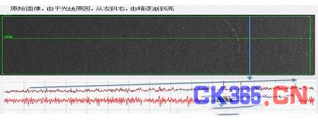
However, the defects after binarization may also be caused by uneven lighting rather than real scratches or cracks. The shadow correction method in Teledyne DALSA's vision software Sherlock can eliminate lighting changes and improve the reliability of crack and scratch detection. It is mainly achieved by space-frequency filtering or input image separation based on a reference image.
A spatial high-pass filter can amplify cracks and scratches with higher spatial frequencies and remove low-frequency variations caused by changes in illumination intensity. Therefore, it can be used to detect cracks and scratches on the surface of a product. However, a high-pass filter also amplifies the surface texture of the part, generating noise on the image, making crack and scratch detection more difficult. Therefore, we should try to remove the lower spatial frequencies instead of amplifying the higher spatial frequencies. Only the higher spatial frequency variations—scratches and cracks—are retained.


Figure 1 Shading correction eliminates grayscale variations caused by lighting changes (top) and improves the reliability of scratch detection (bottom)
The reference map is generated without the parts being placed. This map shows the lighting distribution. Subsequent input images are separated based on the reference map to eliminate the lighting effect. Since the image grayscale is the product of the lighting and the reflection or transmission of the part, the pixel-by-pixel separation method based on the reference map can eliminate the lighting factor and only retain the reflection or transmission factor of the part. This method is widely used for microscopy inspection, but less used in production lines.
Golden Reference Method
Most parts have variations in reflection or transmission that can mask surface scratches and cracks. We extend the idea of the fiducial image to generate a golden reference image by taking multiple images of well-aligned good parts (rather than a blank image) and averaging them. Based on this overall deviation, we can estimate the natural or acceptable variation at each point on the part.
The input component image can be subtracted from the golden reference image to eliminate changes in lighting and component reflection or transmission. This method can be used to set the detection threshold for each point in the image, which is particularly effective when the grayscale structure of the component can be strictly controlled, such as semiconductors. The golden reference image and the component input image must also be corrected for position, rotation, and scale. [page]
Use adaptive filters to remove repeated patterns
The golden reference method can in some cases remove repetitive patterns of components, such as grids. However, if there is a lack of control over the component structure, reflectivity or transmittance, it may produce false signals. The matched filter can solve this problem.
The basic principle of an adaptive filter is to use a filter that matches the spatial frequency of the part's repetitive pattern, filtering out the repetitive pattern and leaving only relatively intact surface defects - optimizing the signal-to-noise ratio of surface defects. Advantages of using an adaptive filter include tolerance for misalignment between the filter and the input image, and tolerance for grayscale variations in the pattern after normalization.
One approach is to use a special algorithm in Teledyne DALSA's vision software Sherlock to convert the repetitive pattern into spatial frequency and generate an adaptive filter. Then, in the spatial frequency domain, the adaptive filter is subtracted from the input image to effectively remove the portion of the input image that matches the filter frequency. If the location and structure of the surface defect do not need to be identified, defect detection can be completed in the spatial frequency domain. Alternatively, the inverse transform method can be used to draw a spatial grayscale image after removing the repetitive pattern, and then perform detection in the resulting spatial domain.
If the spatial frequency of a surface defect overlaps with the spatial frequency of the filter, the defect will be attenuated. If the overlap is large, the signal strength after filtering is not sufficient to ensure reliable defect detection.

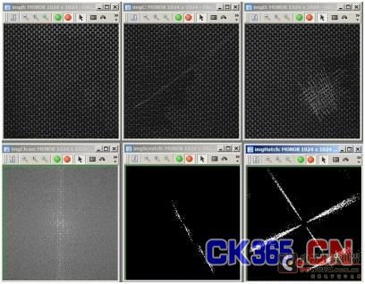
Figure 2 Top (from left): Acceptable parts, single scratch, multiple scratches Bottom (from left): Acceptable parts, single scratch filtered, multiple scratch filtered
Structural Method
Even if the above methods are used, the reliability of detection is often reduced because the defect signal strength is usually too small. The structural method mainly uses the existing information of the defect structure to improve the detection effect. For example, scratches are usually a series of points connected into a line in the image. Therefore, the reliability of scratch detection can be improved by amplifying or accumulating the points on the line. Two structural methods are introduced below.
Mathematical morphology - Modify and detect the shape (morphology) of parts in an image. Erosion is used to strip pixels from the edge of a shiny object. Dilation is used to add pixels to the edge of a shiny object. Suppose a scratch on a surface is brighter than the object itself, and the approximate location of the scratch is known. In this case, a directional dilation operation can be used to expand and enlarge the points on the scratch. Then, a directional erosion operation can be used to thin the resulting lines and reduce the noise pixels that were previously enlarged. Various other morphological operators can also be used to improve the reliability of defect detection when the defect structure is known in advance.

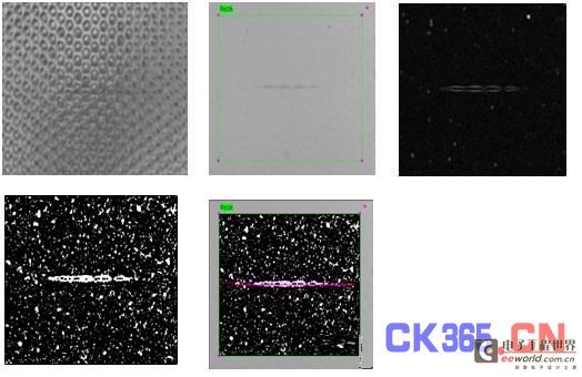
Figure 3 A crack detected using morphology and other methods
Hough Transform - Each pixel outside the detection threshold "votes" for all possible lines of pixels it may be located in. A line of pixels consisting of a certain number of pixels outside the threshold is a scratch or crack. The Hough Transform can be used to detect very weak line signals because it can combine pixel lines composed of multiple pixels. This method is very effective in some cases, but it has the disadvantages of being slow and difficult to set up for detection.

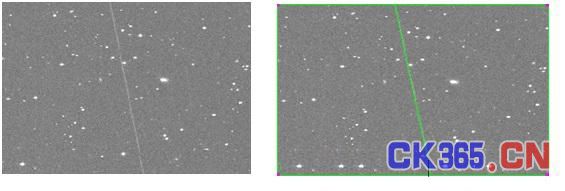
Figure 4 Scratches on a textured work surface material detected using the Hough transform method (green lines on the sample)
Any new surface defect is a challenge. However, with some experience and the right tools, we can overcome the challenge. The detection methods introduced in this article are just the tip of the iceberg in this field.
Previous article:Sigmatek's solutions for automotive engine testing systems
Next article:Mold precision testing technology
- New IsoVu™ Isolated Current Probes: Bringing a New Dimension to Current Measurements
- Modern manufacturing strategies drive continuous improvement in ICT online testing
- Methods for Correlation of Contact and Non-Contact Measurements
- Keysight Technologies Helps Samsung Electronics Successfully Validate FiRa® 2.0 Safe Distance Measurement Test Case
- From probes to power supplies, Tektronix is leading the way in comprehensive innovation in power electronics testing
- Seizing the Opportunities in the Chinese Application Market: NI's Challenges and Answers
- Tektronix Launches Breakthrough Power Measurement Tools to Accelerate Innovation as Global Electrification Accelerates
- Not all oscilloscopes are created equal: Why ADCs and low noise floor matter
- Enable TekHSI high-speed interface function to accelerate the remote transmission of waveform data
- Intel promotes AI with multi-dimensional efforts in technology, application, and ecology
- ChinaJoy Qualcomm Snapdragon Theme Pavilion takes you to experience the new changes in digital entertainment in the 5G era
- Infineon's latest generation IGBT technology platform enables precise control of speed and position
- Two test methods for LED lighting life
- Don't Let Lightning Induced Surges Scare You
- Application of brushless motor controller ML4425/4426
- Easy identification of LED power supply quality
- World's first integrated photovoltaic solar system completed in Israel
- Sliding window mean filter for avr microcontroller AD conversion
- What does call mean in the detailed explanation of ABB robot programming instructions?
- STMicroelectronics discloses its 2027-2028 financial model and path to achieve its 2030 goals
- 2024 China Automotive Charging and Battery Swapping Ecosystem Conference held in Taiyuan
- State-owned enterprises team up to invest in solid-state battery giant
- The evolution of electronic and electrical architecture is accelerating
- The first! National Automotive Chip Quality Inspection Center established
- BYD releases self-developed automotive chip using 4nm process, with a running score of up to 1.15 million
- GEODNET launches GEO-PULSE, a car GPS navigation device
- Should Chinese car companies develop their own high-computing chips?
- Infineon and Siemens combine embedded automotive software platform with microcontrollers to provide the necessary functions for next-generation SDVs
- Continental launches invisible biometric sensor display to monitor passengers' vital signs
- CC2540 learning to send strings
- Lead-free/RoHS latest notice
- Summary of Power Supply Problems Researched by Daniel for Many Years 2 (Benefited a lot)
- EEWORLD University Hall----Live Replay: ADI Energy Storage System Helps Build Electric Vehicle Fast Charging Stations
- Digital Temperature Servo Control System Based on Microcontroller
- Recruiting embedded system engineers
- [Perf-V Evaluation] Study and RTL Simulation Experiment of Hummingbird E203 Open Source SOC
- About the power supply problem of LED constant current chip
- LIN communication, no response error, please help
- Amplifier Distortion

 Machine Vision Algorithms and Applications 2nd Edition
 Fabric defect detection algorithm based on image distance difference
 VBAI2010(Vision Builder for Automated Inspection 2010)


 京公网安备 11010802033920号