Introduction
Frequency refers to the number of times a certain periodic phenomenon is repeated in a unit of time. It is mathematically the reciprocal of time. The precise measurement of time frequency has promoted the development of science, and the development of science has in turn raised the measurement of time frequency to a new level. Especially in recent decades, the measurement accuracy of frequency and time has reached a very high level, which has far exceeded the measurement accuracy of all other physical quantities. Its main application areas include navigation and communication, as well as space technology, industrial production, transportation, scientific research, astronomy and metrology.
In order to meet the requirements of modern technological development, new frequency meters use single-chip microcomputers for data processing. In this way, software replaces complex hardware circuits, simplifying the structure of the instrument and enhancing its functions. This paper presents a simple frequency measurement method based on TMS320F2812 (abbreviated as F2812) DSP. This method effectively utilizes the capture function of the on-chip external event manager of F2812 to capture and count at the effective level transition edge of the measured signal. The circuit is mostly implemented by software settings, with simple calculation, good real-time performance and high measurement accuracy.
1 Measurement method
The commonly used frequency measurement methods mainly include direct frequency measurement method, direct cycle measurement method and multi-cycle measurement method. Although the direct frequency measurement method has higher accuracy in the high frequency band, it has lower accuracy in the low frequency band, while the direct cycle measurement method is just the opposite. The multi-cycle measurement method is to input the measured signal and the standard signal into two counters respectively. Its actual gate time is not a fixed value, but an integer multiple of the measured signal cycle. Therefore, the counting error of ±1 Hz generated when counting the measured signal is eliminated, and its accuracy is only related to the gate time and the standard frequency. Therefore, this design adopts the multi-cycle measurement method as a specific implementation plan.
2 System design
2.1 System hardware design
The overall block diagram of the hardware system is shown in Figure 1. The measured signal is firstly converted into a square wave signal of 0~3.3 V through limiting amplification, DC bias, and shaping circuits, and then enters the DSP to use its timer and capture unit to realize the frequency measurement. After the measurement is completed, on the one hand, the relevant parameters can be set by the keyboard to display the measurement results through the LCD, and on the other hand, the measurement results can be transmitted to the PC through RS-232 to display the measurement results. In addition, in order to improve the reliability of the system, a self-calibration circuit is added. That is, before measurement, a 1 MHz standard pulse signal can be generated through software settings and sent to the input end of the signal conditioning module to detect whether the measurement result is correct, thereby achieving the purpose of self-calibration.
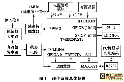
This design uses the F2812 DSP of Texas Instruments (TI) as the core processing unit. F2812 is a high-speed, high-precision industrial control DSP chip launched by TI in recent years. It has a fast computing speed, a working clock frequency of 150 MHz, an instruction cycle of less than 6.67 ns, and low power consumption (core voltage 1.8 V, I/O port voltage 3.3 V). It adopts the Harvard bus structure and has powerful operating capabilities; peripheral devices include 3 32-bit CPU timers, 16-channel 12-bit A/D converter, serial peripheral interface (SPI), 2 serial communication interfaces (SCI), etc. Its on-chip peripheral time manager contains 2 modules (EVA and EVB), each of which includes 2 general timers, 3 full comparison/PWM units, 3 capture units and 1 orthogonal encoding pulse circuit. This design mainly uses 2 general timers (T1 and T2), 2 capture units (CAP1 and CAP3) in EVA, and 1 general timer (T3) in EVB. The specific measurement principle is shown in Figure 2.
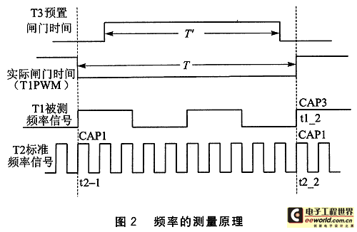
First, set the T3 comparison value (preset gate time is 0.012 8 s), set the T1 comparison value to 1, and enable CAP1. Then enable T1, and when it receives a full cycle of the measured signal, it can generate a comparison output, and at the same time generate a comparison interrupt, read the stack value of CAP1 (that is, the initial value of T2 t2_1), clear the overflow times of T1 and T2, and enable CAP3 and T3. Finally, when the T3 timing ends, with the help of the D flip-flop, when the next rising edge of the measured signal arrives, the comparison output of T1 is cut off, and PDPINTA will be set at the same time, and then the overflow times tlofcount and t2ofcount of T1 and T2 are recorded, and the stack value of CAP1 (that is, the final value t2_2 of T2) and the stack value of CAP3 (that is, the final value tl_2 of T1) are read. Calculate the frequency from the obtained data, and disable T1, T2, CAP1 and CAP3. The frequency calculation formula is:

Note: The capture time base of CAP1 is T2, the capture time base of CAP3 is T1, and the standard frequency signal is 8 times the 150 MHz clock frequency.
2.2 System software design
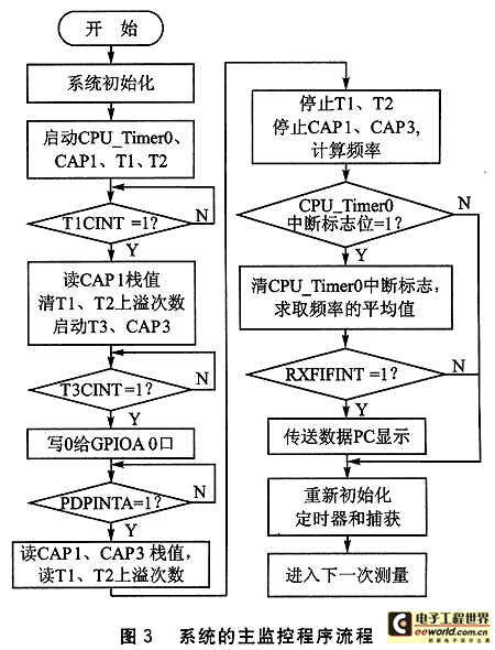
The main monitoring program is the general scheduler of the entire software system, which controls the orderly operation of the program. After the system is powered on or reset, the main program first calls the initialization subroutines of each module, mainly including GPIO initialization, PIE initialization, EV initialization and SCI initialization. After the system initialization is completed, the main program starts CPU_Timer0, enables the overflow interrupts of T1 and T2, starts CAP1, sets the comparison value of T1 to 1, waits for T1CINT to be set, and starts measuring the frequency. In order to reduce the random errors generated during the measurement process, the measured results are averaged. CPU_Timer0 is used to generate a certain time period (0.6s). After the end of this period (CPU_Timer0 interrupt flag is set), the measurement results recorded in this period are averaged. At this time, if the host computer sends a receive request, the corresponding data is transmitted to the PC for display. Then, the timer and capture unit are reinitialized to enter the next round of measurement. The main monitoring program flow is shown in Figure 3. [page]
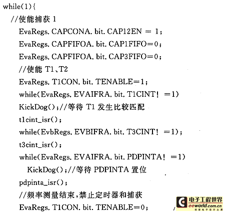
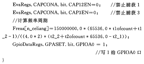
Part of the source code for frequency measurement is as follows:
3 Error analysis and test results
3.1 Quantization error
Assume that the frequency of the measured signal is Fx, its true value is Fxe, and the standard frequency is Fs. In a measurement, the preset gate time is T′, Tpr is the actual gate time, the measured signal count value is Nx, and the standard frequency signal count value is Ns. The
start and stop time of the Fx count is triggered by the rising edge of the signal. Within the T′ time, the count of Fx Nx is error-free, and the count of Fs Ns is assumed to differ by N pulses, that is, |△et|≤n.
Since Fx/Nx=Fs/Ns, Fxe/Nx=Fs/(Ns+△et), according to the relative error formula:
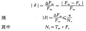
Therefore, the following conclusions can be drawn:
① The relative measurement error is independent of the frequency of the measured signal.
② Increasing T' or increasing Fs can increase Ns, reduce the measurement error, and improve the measurement accuracy. In this design, the preset gate time limits the minimum measurement accuracy.
③ The n in the error analysis is mainly determined by the time required for the hardware to cut off T1PWM, which is a small integer constant. If the preset gate time Tpr = 0.012 8 s, then

Even if n is a small integer constant other than 1, the accuracy can still be maintained within one hundred thousandth, and can be further improved with the appropriate extension of the preset gate time. [page]
3.2 Principle error of measurement and standard frequency error
This measurement principle is similar to the multi-cycle synchronous measurement principle. The main principle error comes from the low-level jump generated by the D trigger to cut off T1PWM when the measurement is about to end, so that it generates a jump of the rising edge captured by CAP1 and CAP3 at the same time. This period is mainly determined by the reaction time of the D trigger. During the measurement process, this part of the error can be overcome by appropriately increasing the preset gate time. At the same time, considering the high-speed clock frequency inside the DSP, this will not significantly increase the measurement time, but it will achieve the purpose of weakening the influence of this error and increasing the measurement accuracy. The
standard frequency error is △Fs/Fs. Because the stability of the crystal is very high, the standard frequency error can be calibrated, and the high-speed clock frequency inside the DSP has been appropriately divided, so compared with the quantization error, the calibrated standard frequency error can be ignored.
3.3 Test results
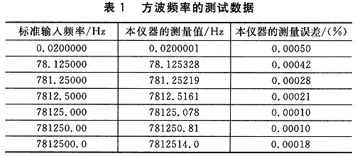
A function signal generator (Tektronix AFG3010; accuracy 0.000 1%) was used to generate a square wave signal, and the frequency was measured with the designed frequency meter to find the error. The measurement accuracy of this frequency measurement system can reach 0.01%. According to the error analysis, the maximum error of the system occurs when the preset gate time just fills an integer number of measured signals, that is, when the frequency is 78.125 Hz or its integer multiples, so these points are selected for testing. The actual test data is listed in Table 1.
4 Conclusion
This paper focuses on the design scheme, hardware composition, and software design of the digital frequency meter using the Modbus protocol to achieve communication between the host and the slave. Features are:
① In terms of frequency measurement principle, due to the use of multi-cycle measurement principle, the ±1 counting error generated when counting the measured signal is eliminated, and its accuracy is only related to the gate time and the standard frequency, overcoming the shortcomings of the traditional frequency measurement method or cycle measurement method, and achieving wide-range, high-precision frequency measurement. At the same time, due to the existence of the preset gate time, it is ensured that when the measured frequency switches back and forth between the frequency bands, the system responds sensitively and has good following performance.
② In terms of the overall design of the system, the internal resources of the F2812 DSP are fully utilized, that is, the timer and capture unit in the event manager are used to complete the frequency measurement; the PWM output is used to realize the design of the self-test circuit; and the serial communication module is used to complete the communication between the host and the slave. In terms of the display of the measurement results, RS232 is used, and the communication protocol adopts the Modbus protocol to achieve the communication between the slave and the host, and the measurement results are displayed in the host.
This paper only discusses how to measure the frequency of a single-channel signal. For multi-channel signals, you can first pass them through an AND gate, use software to determine which signal is which, and then use this design method to measure. The error problem caused by this situation needs further discussion. This paper only gives a preliminary exploration.
References
1. Zhou Wenshui Research and Implementation of Phase Broadband Frequency Measurement Principle [Dissertation]
2. Xu Kejun. Li Guoli Electrical Test Basics 2002
3. Zhang Zhiwen. Tian Yingfeng Research on High-Precision Frequency Measurement System Based on DSP [Journal Article] - Journal of Xi'an University of Technology 2007 (2)
4. Texas Instruments Incorporated TMS320F28x DSP Family User's Guide
5. Liang Wenhai Using Single-Chip Microcomputer to Implement Dual Counter Multi-Cycle Synchronization Method Frequency Measurement [Journal Article] - Modern Electronic Technology 2007 (7)
6. Zheng Jie. Tao Weiqing A Frequency Measurement Method Based on TMS320F2812 Event Manager [Journal Article] - Microcomputer Information 2006 (5)
Keywords:TMS320F2812
Reference address:Design of Digital Frequency Meter Based on TMS320F2812
Frequency refers to the number of times a certain periodic phenomenon is repeated in a unit of time. It is mathematically the reciprocal of time. The precise measurement of time frequency has promoted the development of science, and the development of science has in turn raised the measurement of time frequency to a new level. Especially in recent decades, the measurement accuracy of frequency and time has reached a very high level, which has far exceeded the measurement accuracy of all other physical quantities. Its main application areas include navigation and communication, as well as space technology, industrial production, transportation, scientific research, astronomy and metrology.
In order to meet the requirements of modern technological development, new frequency meters use single-chip microcomputers for data processing. In this way, software replaces complex hardware circuits, simplifying the structure of the instrument and enhancing its functions. This paper presents a simple frequency measurement method based on TMS320F2812 (abbreviated as F2812) DSP. This method effectively utilizes the capture function of the on-chip external event manager of F2812 to capture and count at the effective level transition edge of the measured signal. The circuit is mostly implemented by software settings, with simple calculation, good real-time performance and high measurement accuracy.
1 Measurement method
The commonly used frequency measurement methods mainly include direct frequency measurement method, direct cycle measurement method and multi-cycle measurement method. Although the direct frequency measurement method has higher accuracy in the high frequency band, it has lower accuracy in the low frequency band, while the direct cycle measurement method is just the opposite. The multi-cycle measurement method is to input the measured signal and the standard signal into two counters respectively. Its actual gate time is not a fixed value, but an integer multiple of the measured signal cycle. Therefore, the counting error of ±1 Hz generated when counting the measured signal is eliminated, and its accuracy is only related to the gate time and the standard frequency. Therefore, this design adopts the multi-cycle measurement method as a specific implementation plan.
2 System design
2.1 System hardware design
The overall block diagram of the hardware system is shown in Figure 1. The measured signal is firstly converted into a square wave signal of 0~3.3 V through limiting amplification, DC bias, and shaping circuits, and then enters the DSP to use its timer and capture unit to realize the frequency measurement. After the measurement is completed, on the one hand, the relevant parameters can be set by the keyboard to display the measurement results through the LCD, and on the other hand, the measurement results can be transmitted to the PC through RS-232 to display the measurement results. In addition, in order to improve the reliability of the system, a self-calibration circuit is added. That is, before measurement, a 1 MHz standard pulse signal can be generated through software settings and sent to the input end of the signal conditioning module to detect whether the measurement result is correct, thereby achieving the purpose of self-calibration.

This design uses the F2812 DSP of Texas Instruments (TI) as the core processing unit. F2812 is a high-speed, high-precision industrial control DSP chip launched by TI in recent years. It has a fast computing speed, a working clock frequency of 150 MHz, an instruction cycle of less than 6.67 ns, and low power consumption (core voltage 1.8 V, I/O port voltage 3.3 V). It adopts the Harvard bus structure and has powerful operating capabilities; peripheral devices include 3 32-bit CPU timers, 16-channel 12-bit A/D converter, serial peripheral interface (SPI), 2 serial communication interfaces (SCI), etc. Its on-chip peripheral time manager contains 2 modules (EVA and EVB), each of which includes 2 general timers, 3 full comparison/PWM units, 3 capture units and 1 orthogonal encoding pulse circuit. This design mainly uses 2 general timers (T1 and T2), 2 capture units (CAP1 and CAP3) in EVA, and 1 general timer (T3) in EVB. The specific measurement principle is shown in Figure 2.

First, set the T3 comparison value (preset gate time is 0.012 8 s), set the T1 comparison value to 1, and enable CAP1. Then enable T1, and when it receives a full cycle of the measured signal, it can generate a comparison output, and at the same time generate a comparison interrupt, read the stack value of CAP1 (that is, the initial value of T2 t2_1), clear the overflow times of T1 and T2, and enable CAP3 and T3. Finally, when the T3 timing ends, with the help of the D flip-flop, when the next rising edge of the measured signal arrives, the comparison output of T1 is cut off, and PDPINTA will be set at the same time, and then the overflow times tlofcount and t2ofcount of T1 and T2 are recorded, and the stack value of CAP1 (that is, the final value t2_2 of T2) and the stack value of CAP3 (that is, the final value tl_2 of T1) are read. Calculate the frequency from the obtained data, and disable T1, T2, CAP1 and CAP3. The frequency calculation formula is:

Note: The capture time base of CAP1 is T2, the capture time base of CAP3 is T1, and the standard frequency signal is 8 times the 150 MHz clock frequency.
2.2 System software design
The main monitoring program is the general scheduler of the entire software system, which controls the orderly operation of the program. After the system is powered on or reset, the main program first calls the initialization subroutines of each module, mainly including GPIO initialization, PIE initialization, EV initialization and SCI initialization. After the system initialization is completed, the main program starts CPU_Timer0, enables the overflow interrupts of T1 and T2, starts CAP1, sets the comparison value of T1 to 1, waits for T1CINT to be set, and starts measuring the frequency. In order to reduce the random errors generated during the measurement process, the measured results are averaged. CPU_Timer0 is used to generate a certain time period (0.6s). After the end of this period (CPU_Timer0 interrupt flag is set), the measurement results recorded in this period are averaged. At this time, if the host computer sends a receive request, the corresponding data is transmitted to the PC for display. Then, the timer and capture unit are reinitialized to enter the next round of measurement. The main monitoring program flow is shown in Figure 3. [page]

Part of the source code for frequency measurement is as follows:


3 Error analysis and test results
3.1 Quantization error
Assume that the frequency of the measured signal is Fx, its true value is Fxe, and the standard frequency is Fs. In a measurement, the preset gate time is T′, Tpr is the actual gate time, the measured signal count value is Nx, and the standard frequency signal count value is Ns. The
start and stop time of the Fx count is triggered by the rising edge of the signal. Within the T′ time, the count of Fx Nx is error-free, and the count of Fs Ns is assumed to differ by N pulses, that is, |△et|≤n.
Since Fx/Nx=Fs/Ns, Fxe/Nx=Fs/(Ns+△et), according to the relative error formula:

Therefore, the following conclusions can be drawn:
① The relative measurement error is independent of the frequency of the measured signal.
② Increasing T' or increasing Fs can increase Ns, reduce the measurement error, and improve the measurement accuracy. In this design, the preset gate time limits the minimum measurement accuracy.
③ The n in the error analysis is mainly determined by the time required for the hardware to cut off T1PWM, which is a small integer constant. If the preset gate time Tpr = 0.012 8 s, then

Even if n is a small integer constant other than 1, the accuracy can still be maintained within one hundred thousandth, and can be further improved with the appropriate extension of the preset gate time. [page]
3.2 Principle error of measurement and standard frequency error
This measurement principle is similar to the multi-cycle synchronous measurement principle. The main principle error comes from the low-level jump generated by the D trigger to cut off T1PWM when the measurement is about to end, so that it generates a jump of the rising edge captured by CAP1 and CAP3 at the same time. This period is mainly determined by the reaction time of the D trigger. During the measurement process, this part of the error can be overcome by appropriately increasing the preset gate time. At the same time, considering the high-speed clock frequency inside the DSP, this will not significantly increase the measurement time, but it will achieve the purpose of weakening the influence of this error and increasing the measurement accuracy. The
standard frequency error is △Fs/Fs. Because the stability of the crystal is very high, the standard frequency error can be calibrated, and the high-speed clock frequency inside the DSP has been appropriately divided, so compared with the quantization error, the calibrated standard frequency error can be ignored.
3.3 Test results
A function signal generator (Tektronix AFG3010; accuracy 0.000 1%) was used to generate a square wave signal, and the frequency was measured with the designed frequency meter to find the error. The measurement accuracy of this frequency measurement system can reach 0.01%. According to the error analysis, the maximum error of the system occurs when the preset gate time just fills an integer number of measured signals, that is, when the frequency is 78.125 Hz or its integer multiples, so these points are selected for testing. The actual test data is listed in Table 1.

4 Conclusion
This paper focuses on the design scheme, hardware composition, and software design of the digital frequency meter using the Modbus protocol to achieve communication between the host and the slave. Features are:
① In terms of frequency measurement principle, due to the use of multi-cycle measurement principle, the ±1 counting error generated when counting the measured signal is eliminated, and its accuracy is only related to the gate time and the standard frequency, overcoming the shortcomings of the traditional frequency measurement method or cycle measurement method, and achieving wide-range, high-precision frequency measurement. At the same time, due to the existence of the preset gate time, it is ensured that when the measured frequency switches back and forth between the frequency bands, the system responds sensitively and has good following performance.
② In terms of the overall design of the system, the internal resources of the F2812 DSP are fully utilized, that is, the timer and capture unit in the event manager are used to complete the frequency measurement; the PWM output is used to realize the design of the self-test circuit; and the serial communication module is used to complete the communication between the host and the slave. In terms of the display of the measurement results, RS232 is used, and the communication protocol adopts the Modbus protocol to achieve the communication between the slave and the host, and the measurement results are displayed in the host.
This paper only discusses how to measure the frequency of a single-channel signal. For multi-channel signals, you can first pass them through an AND gate, use software to determine which signal is which, and then use this design method to measure. The error problem caused by this situation needs further discussion. This paper only gives a preliminary exploration.
References
1. Zhou Wenshui Research and Implementation of Phase Broadband Frequency Measurement Principle [Dissertation]
2. Xu Kejun. Li Guoli Electrical Test Basics 2002
3. Zhang Zhiwen. Tian Yingfeng Research on High-Precision Frequency Measurement System Based on DSP [Journal Article] - Journal of Xi'an University of Technology 2007 (2)
4. Texas Instruments Incorporated TMS320F28x DSP Family User's Guide
5. Liang Wenhai Using Single-Chip Microcomputer to Implement Dual Counter Multi-Cycle Synchronization Method Frequency Measurement [Journal Article] - Modern Electronic Technology 2007 (7)
6. Zheng Jie. Tao Weiqing A Frequency Measurement Method Based on TMS320F2812 Event Manager [Journal Article] - Microcomputer Information 2006 (5)
Previous article:Design of a high-precision digitally controlled bipolar constant current source circuit
Next article:System Testing and Reliability Assessment of Embedded Systems
Recommended ReadingLatest update time:2024-11-25 04:14
Design of high-precision servo position loop based on TMS320F2812
introduction
Machine tools are the mother machine and the engine of the equipment manufacturing industry. my country's "Eleventh Five-Year Plan" development plan clearly stipulates that the domestic market share of domestic CNC machine tools must reach 60%, and the gap between high-end products and internat
[Embedded]
Design of leakage current test system based on TMS320F2812

0 Introduction Leakage current refers to the current formed between mutually insulated metal parts in electrical equipment, or between live parts and grounded parts, through the surrounding medium or insulating surface when there is no fault voltage applied. It also includes the current from the equipment through the
[Test Measurement]

Design of driving power supply for giant magnetostrictive transducer

The rare earth giant magnetostrictive transducer is a device that converts electromagnetic energy into mechanical vibration using giant magnetostrictive materials. Compared with the widely used piezoelectric ceramic transducer, it has the advantages of wide working range, high conversion efficiency, and fast response s
[Microcontroller]

Portable Dynamic Signal Analyzer Based on TMS320F2812
1 Introduction
In the field of electronic measurement, dynamic signal analyzers are called "RF multimeters" in the frequency domain, which shows their importance and wide application. Dynamic signal analysis is to convert time domain signals into frequency domain for processing, which generally requires the
[Embedded]
A method to improve the accuracy of TMS320F2812 ADC
TMS320F2812 is a 32-bit high-performance digital signal processor (DSP) with a main frequency of up to 150 MHz launched by Texas Instruments (TI), which integrates an ADC conversion module. The ADC module is a 12-bit analog-to-digital converter with a pipeline structure, built-in dual sample-and-hold (S/H), and can
[Embedded]
- Popular Resources
- Popular amplifiers
Recommended Content
Latest Test Measurement Articles
- New IsoVu™ Isolated Current Probes: Bringing a New Dimension to Current Measurements
- Modern manufacturing strategies drive continuous improvement in ICT online testing
- Methods for Correlation of Contact and Non-Contact Measurements
- Keysight Technologies Helps Samsung Electronics Successfully Validate FiRa® 2.0 Safe Distance Measurement Test Case
- From probes to power supplies, Tektronix is leading the way in comprehensive innovation in power electronics testing
- Seizing the Opportunities in the Chinese Application Market: NI's Challenges and Answers
- Tektronix Launches Breakthrough Power Measurement Tools to Accelerate Innovation as Global Electrification Accelerates
- Not all oscilloscopes are created equal: Why ADCs and low noise floor matter
- Enable TekHSI high-speed interface function to accelerate the remote transmission of waveform data
MoreSelected Circuit Diagrams
MorePopular Articles
- Intel promotes AI with multi-dimensional efforts in technology, application, and ecology
- ChinaJoy Qualcomm Snapdragon Theme Pavilion takes you to experience the new changes in digital entertainment in the 5G era
- Infineon's latest generation IGBT technology platform enables precise control of speed and position
- Two test methods for LED lighting life
- Don't Let Lightning Induced Surges Scare You
- Application of brushless motor controller ML4425/4426
- Easy identification of LED power supply quality
- World's first integrated photovoltaic solar system completed in Israel
- Sliding window mean filter for avr microcontroller AD conversion
- What does call mean in the detailed explanation of ABB robot programming instructions?
MoreDaily News
- CATL releases October battle report
- Battery industry in October 2024: growth momentum remains unabated!
- Mercedes-Benz will launch the eCitaro equipped with NMC4 batteries to provide high energy density and long life
- Many companies have announced progress on solid-state batteries. When will solid-state batteries go into mass production?
- Xsens Sirius Series Inertial Sensors Enable 3D Inertial Navigation in Harsh Environments
- Infineon's Automotive Landscape: From Hardware to Systems
- STMicroelectronics discloses its 2027-2028 financial model and path to achieve its 2030 goals
- 2024 China Automotive Charging and Battery Swapping Ecosystem Conference held in Taiyuan
- State-owned enterprises team up to invest in solid-state battery giant
- The evolution of electronic and electrical architecture is accelerating
Guess you like
- Kill TPS54340
- Electronic ballast for automotive high intensity discharge lamps
- I have a hard time without a college diploma.
- Why is the voltage ringing spike of MOSFET different in boost and buck mode?
- The circuit for discharging the PFC output capacitor is shown in Figure 2.
- Basic syntax of Verilog HDL
- Dual Transformation
- Thanks to okhxyyo for searching and fish001 for sharing
- Please advise, is it easy to pass the postgraduate examination and graduate, and how useful is the degree certificate?
- About the LAUNCHXL-F28379D Development Kit

 Vehicle Electronic Control Technology 2018 Edition


 京公网安备 11010802033920号