When repairing household electronic products, especially color TV sets, it is often necessary to measure the voltage value of the voltage regulator diode, and measure the quality of electronic components such as thyristors, photocouplers, ceramic oscillators, quartz crystal oscillators, infrared remote control receivers, infrared remote control transmitters, and line output transformers. The parameters or quality of these electronic components cannot be directly detected by a multimeter. The multifunctional electronic component detection circuit board introduced in this article can be used to simply and accurately measure their parameters or quality, which brings great convenience to the maintenance work. The
multifunctional electronic component detection circuit board consists of seven unit circuits, which are assembled on a 10cm×6.5cm universal circuit board and share a set of power input circuits. The power supply end of each unit circuit is connected to the power input circuit through a short-circuit plug. With a DC power supply with adjustable output voltage and a multimeter, it can be easily tested.
Voltage regulator diode detection circuit
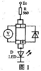
The measurement circuit of the voltage regulator diode voltage value is shown in Figure 1. The socket for inserting the component to be tested in the figure is modified from an integrated circuit socket. Insert the tested Zener diode into the jack according to the polarity required in Figure 1, and use the DC voltage range of the multimeter to measure the DC voltage across the Zener diode. First adjust the output voltage of the DC power supply to the lowest, turn on the power, and adjust the input voltage from low to high. When the light-emitting diode D emits normally, adjust the input voltage within a certain range. When the voltage across the Zener diode remains approximately unchanged, the indicated value of the multimeter is the voltage stabilization value of the tested Zener diode.
Thyristor detection circuit
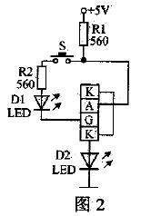
The thyristor detection circuit is shown in Figure 2. First use a multimeter to detect the A, G, and K poles of the tested thyristor, and then insert the A, G, and K pins of the tested thyristor into the corresponding jacks. Turn on the power. When the button switch S is not pressed, the light-emitting diode D2 does not emit light. When the button switch S is pressed, if the light-emitting diode D2 can continue to emit light, the tested thyristor is good.
Photocoupler detection circuit
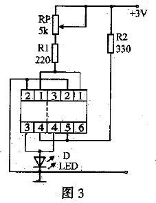
The photocoupler detection circuit is shown in Figure 3. The four-pin photocoupler such as TLP621 can be inserted into the four-pin jack at the left end of the socket, and the six-pin photocoupler such as TLP332 can be inserted into the six-pin jack at the right end of the socket. After the power is turned on, the power supply provides a forward voltage to the light-emitting diode in the IC through RP and R1. The light-emitting diode emits light, turning on the phototransistor in the IC, and the light-emitting diode D connected to the 3rd pin emits light. If the brightness of the light-emitting diode can change when adjusting RP, the photocoupler under test is good.
Ceramic oscillator detection circuit The
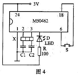
ceramic oscillator detection circuit is shown in Figure 4. The external component 455kHz or 500kHz ceramic oscillator X, C1, C2 and the internal circuit of the 2nd and 3rd pins of the integrated circuit M50462 form a 455kHz or 500kHz oscillation circuit. The 455kHz or 500kHz ceramic oscillator to be tested is inserted into the jack, the power is turned on, and the button switch S is pressed. If the light-emitting diode can flash continuously, it means that the ceramic oscillator to be tested is good. [page]
Quartz crystal oscillator detection circuit
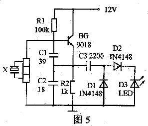
The quartz crystal oscillator detection circuit is shown in Figure 5. BG and C1, C2, quartz crystal oscillator X form a high-frequency oscillation circuit, and C3, D1 and D2 form a double voltage rectifier circuit. Insert the quartz crystal oscillator to be tested into the jack, turn on the power, if the light-emitting diode D3 can continue to emit light, the quartz crystal oscillator to be tested is good.
When the resonant frequency of the ceramic oscillator or quartz crystal oscillator changes, it cannot be detected, but this damage is extremely small. If you need to further determine whether the resonant frequency has changed, you can use the substitution method.
Infrared remote control receiver and transmitter detection circuit
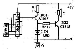
The detection circuit of the infrared remote control receiver and infrared remote control transmitter is shown in Figure 6. In the figure, Y is a cylindrical small volume buzzer with a diameter of 1cm and a height of about 1cm. The jack labels "+" and "-" represent the power supply end of the remote control receiver, and "o" represents the signal output end of the remote control receiver. If you test an integrated three-terminal infrared remote control receiver, insert the three pins of the remote control receiver to be tested into the corresponding jacks, turn on the power, use a good infrared remote control transmitter to face the remote control receiver, and press any button of the remote control transmitter. If D1 can flash and the buzzer Y sounds at the same time, the infrared remote control receiver to be tested is good. If you want to detect the quality of the infrared remote control transmitter, you need to insert a good infrared remote control receiver into the socket. When you press any button of the infrared transmitter under test, the light-emitting diode D1 can flash and the buzzer sounds at the same time, then the infrared remote control transmitter under test is good.
Line output transformer detection circuit The
line output transformer detection circuit is shown in Figure 7. The 555 integrated timer and external components form a multivibrator. Adjusting RP can generate a square wave pulse of 12.5 to 25kHz, which is output from pin 3 through C3 coupling as the excitation pulse of the FBT primary coil electrical resonance. C3 and the FBT primary coil form a series resonant circuit.
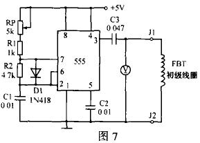
Connect a good FBT primary coil to the output terminals J1 and J2. When the power is turned on, use the AC voltage block of the pointer multimeter to monitor the voltage at both ends of the FBT primary coil. Adjust RP to maximize the indication of the voltmeter. The maximum indication is generally around 26V. When measured with the 200V AC voltage block of the digital voltmeter, the maximum indication is generally around 50V. When a piece of wire is passed through the magnetic core of the FBT and the two ends are short-circuited to simulate the short-circuit fault of the FBT coil, the multimeter reading drops to about 3V. The indication
value of the multimeter is not necessarily exactly equal to the effective value of a sine wave of about 15kHz (when resonating, the two ends of the FBT are measured by an oscilloscope to be a sine wave with an amplitude of 80Vpp). However, when a good FBT is connected, the indication value of the voltmeter is about 26V. When an FBT with a short-circuit between coil turns is connected, the indication value of the voltmeter is generally only about 5V. The difference is very large and will not affect the accurate judgment of whether the FBT coil turns are short-circuited.
Reference address:Multifunctional electronic component detection circuit
multifunctional electronic component detection circuit board consists of seven unit circuits, which are assembled on a 10cm×6.5cm universal circuit board and share a set of power input circuits. The power supply end of each unit circuit is connected to the power input circuit through a short-circuit plug. With a DC power supply with adjustable output voltage and a multimeter, it can be easily tested.
Voltage regulator diode detection circuit
The measurement circuit of the voltage regulator diode voltage value is shown in Figure 1. The socket for inserting the component to be tested in the figure is modified from an integrated circuit socket. Insert the tested Zener diode into the jack according to the polarity required in Figure 1, and use the DC voltage range of the multimeter to measure the DC voltage across the Zener diode. First adjust the output voltage of the DC power supply to the lowest, turn on the power, and adjust the input voltage from low to high. When the light-emitting diode D emits normally, adjust the input voltage within a certain range. When the voltage across the Zener diode remains approximately unchanged, the indicated value of the multimeter is the voltage stabilization value of the tested Zener diode.

Thyristor detection circuit
The thyristor detection circuit is shown in Figure 2. First use a multimeter to detect the A, G, and K poles of the tested thyristor, and then insert the A, G, and K pins of the tested thyristor into the corresponding jacks. Turn on the power. When the button switch S is not pressed, the light-emitting diode D2 does not emit light. When the button switch S is pressed, if the light-emitting diode D2 can continue to emit light, the tested thyristor is good.

Photocoupler detection circuit
The photocoupler detection circuit is shown in Figure 3. The four-pin photocoupler such as TLP621 can be inserted into the four-pin jack at the left end of the socket, and the six-pin photocoupler such as TLP332 can be inserted into the six-pin jack at the right end of the socket. After the power is turned on, the power supply provides a forward voltage to the light-emitting diode in the IC through RP and R1. The light-emitting diode emits light, turning on the phototransistor in the IC, and the light-emitting diode D connected to the 3rd pin emits light. If the brightness of the light-emitting diode can change when adjusting RP, the photocoupler under test is good.

Ceramic oscillator detection circuit The
ceramic oscillator detection circuit is shown in Figure 4. The external component 455kHz or 500kHz ceramic oscillator X, C1, C2 and the internal circuit of the 2nd and 3rd pins of the integrated circuit M50462 form a 455kHz or 500kHz oscillation circuit. The 455kHz or 500kHz ceramic oscillator to be tested is inserted into the jack, the power is turned on, and the button switch S is pressed. If the light-emitting diode can flash continuously, it means that the ceramic oscillator to be tested is good. [page]

Quartz crystal oscillator detection circuit
The quartz crystal oscillator detection circuit is shown in Figure 5. BG and C1, C2, quartz crystal oscillator X form a high-frequency oscillation circuit, and C3, D1 and D2 form a double voltage rectifier circuit. Insert the quartz crystal oscillator to be tested into the jack, turn on the power, if the light-emitting diode D3 can continue to emit light, the quartz crystal oscillator to be tested is good.

When the resonant frequency of the ceramic oscillator or quartz crystal oscillator changes, it cannot be detected, but this damage is extremely small. If you need to further determine whether the resonant frequency has changed, you can use the substitution method.
Infrared remote control receiver and transmitter detection circuit
The detection circuit of the infrared remote control receiver and infrared remote control transmitter is shown in Figure 6. In the figure, Y is a cylindrical small volume buzzer with a diameter of 1cm and a height of about 1cm. The jack labels "+" and "-" represent the power supply end of the remote control receiver, and "o" represents the signal output end of the remote control receiver. If you test an integrated three-terminal infrared remote control receiver, insert the three pins of the remote control receiver to be tested into the corresponding jacks, turn on the power, use a good infrared remote control transmitter to face the remote control receiver, and press any button of the remote control transmitter. If D1 can flash and the buzzer Y sounds at the same time, the infrared remote control receiver to be tested is good. If you want to detect the quality of the infrared remote control transmitter, you need to insert a good infrared remote control receiver into the socket. When you press any button of the infrared transmitter under test, the light-emitting diode D1 can flash and the buzzer sounds at the same time, then the infrared remote control transmitter under test is good.

Line output transformer detection circuit The
line output transformer detection circuit is shown in Figure 7. The 555 integrated timer and external components form a multivibrator. Adjusting RP can generate a square wave pulse of 12.5 to 25kHz, which is output from pin 3 through C3 coupling as the excitation pulse of the FBT primary coil electrical resonance. C3 and the FBT primary coil form a series resonant circuit.

Connect a good FBT primary coil to the output terminals J1 and J2. When the power is turned on, use the AC voltage block of the pointer multimeter to monitor the voltage at both ends of the FBT primary coil. Adjust RP to maximize the indication of the voltmeter. The maximum indication is generally around 26V. When measured with the 200V AC voltage block of the digital voltmeter, the maximum indication is generally around 50V. When a piece of wire is passed through the magnetic core of the FBT and the two ends are short-circuited to simulate the short-circuit fault of the FBT coil, the multimeter reading drops to about 3V. The indication
value of the multimeter is not necessarily exactly equal to the effective value of a sine wave of about 15kHz (when resonating, the two ends of the FBT are measured by an oscilloscope to be a sine wave with an amplitude of 80Vpp). However, when a good FBT is connected, the indication value of the voltmeter is about 26V. When an FBT with a short-circuit between coil turns is connected, the indication value of the voltmeter is generally only about 5V. The difference is very large and will not affect the accurate judgment of whether the FBT coil turns are short-circuited.
Previous article:Techniques for measuring resistance of electronic components
Next article:Digital multimeter to detect capacitors
- Popular Resources
- Popular amplifiers
Recommended Content
Latest Test Measurement Articles
- Seizing the Opportunities in the Chinese Application Market: NI's Challenges and Answers
- Tektronix Launches Breakthrough Power Measurement Tools to Accelerate Innovation as Global Electrification Accelerates
- Not all oscilloscopes are created equal: Why ADCs and low noise floor matter
- Enable TekHSI high-speed interface function to accelerate the remote transmission of waveform data
- How to measure the quality of soft start thyristor
- How to use a multimeter to judge whether a soft starter is good or bad
- What are the advantages and disadvantages of non-contact temperature sensors?
- In what situations are non-contact temperature sensors widely used?
- How non-contact temperature sensors measure internal temperature
MoreSelected Circuit Diagrams
MorePopular Articles
- LED chemical incompatibility test to see which chemicals LEDs can be used with
- Application of ARM9 hardware coprocessor on WinCE embedded motherboard
- What are the key points for selecting rotor flowmeter?
- LM317 high power charger circuit
- A brief analysis of Embest's application and development of embedded medical devices
- Single-phase RC protection circuit
- stm32 PVD programmable voltage monitor
- Introduction and measurement of edge trigger and level trigger of 51 single chip microcomputer
- Improved design of Linux system software shell protection technology
- What to do if the ABB robot protection device stops
MoreDaily News
- Detailed explanation of intelligent car body perception system
- How to solve the problem that the servo drive is not enabled
- Why does the servo drive not power on?
- What point should I connect to when the servo is turned on?
- How to turn on the internal enable of Panasonic servo drive?
- What is the rigidity setting of Panasonic servo drive?
- How to change the inertia ratio of Panasonic servo drive
- What is the inertia ratio of the servo motor?
- Is it better for the motor to have a large or small moment of inertia?
- What is the difference between low inertia and high inertia of servo motors?
Guess you like
- The original material is discontinued, the project still needs maintenance, looking to buy Mai Chong A5D3X core board
- MSP430 MCU Development Record (3)
- 【Canaan K510】+Unboxing Introduction
- TI reference designs bring more imagination to next-generation home appliances
- The fourth model
- Free draw! Tektronix will build your first oscilloscope in your life, and there are also speakers, wireless chargers, and telescopes waiting for you!
- 【K210 Series】1. Show off the K210 development board
- Baidu engineer illegally controlled the company's server to "mine": made a profit of 100,000 in 4 months and was sentenced to 3 years in prison
- Allwinner V5 Data --- Lindeni V5 Development Board
- Hetai ESK32-360 development board "pats" you, free evaluation is waiting for you!

 MAX439CPA


 京公网安备 11010802033920号