Currently, TD-LTE, FDD-LTE, and LTE-Advanced (LTE-A) wireless technologies use several different multiple-input, multiple-output (MIMO) techniques. Given the increasing complexity of MIMO systems, the associated test methods will become more challenging. For example, currently deployed MIMO technologies use two antennas to improve channel performance; some LTE groups are pioneering eight-antenna technology to achieve higher performance. These advanced technologies will make the choice of test methods even more critical.
To find the right method, it is necessary to fully understand the antenna technology used in each version of LTE. For example, beamforming is a key feature of TD-LTE. Although it is an attractive transmission solution in some scenarios (such as open rural areas or hotspot coverage), it is not always the best method. Beamforming can improve the signal-to-noise ratio (SNR) of the cell reception signal, thereby expanding coverage or improving the user experience in the cell edge area. It can also spatially confine the signal to minimize interference. However, beamforming does not increase data rates in areas with sufficient signal-to-noise ratio.
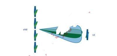
By spatially multiplexing simultaneous data streams, MIMO can increase data throughput in low-correlation, high-SNR channel conditions. To optimize MIMO data rates, TD-LTE uses eight antenna assemblies. In Figure 1, four antennas (shown in blue) are physically polarized at the same angle, while the other four antennas (shown in green) are physically orthogonal to the first four.

Figure 1: This figure shows a TD-LTE eNodeB antenna configuration that can be used to optimize MIMO data rates.
The two sets of four antenna assemblies can enhance the signal-to-noise ratio by forming a beam directed to a specific user equipment (UE). The two orthogonally polarized beams effectively mimic two antennas with low correlation, even if the actual spatial correlation is high. Therefore, this antenna configuration can extend the coverage area, making high data rate transmission possible (Figure 2). Figure 2

: An 8×2 beamforming system forms orthogonally polarized beams.
In addition to TD-LTE, the eight-antenna technology can also be used for FDD-LTE. Network operators can use this antenna configuration to enhance uplink reception by compensating for the link budget limitations of low-power user equipment. The RAN1 working group of 3GPP is actively discussing the actual deployment of eight-antenna technology in LTE-A.
Antenna patterns, or the signal gain of an antenna array in each direction, are often overlooked in traditional performance testing. This is partly because antennas are often assumed to be omnidirectional in traditional testing of single-input single-output (SISO) systems. This is not true for most base stations. Directivity of signal strength plays an important role in MIMO spatial channels, and even more so in beamforming applications. Therefore, careful consideration of antenna patterns is critical when testing eight-antenna systems.
To fully leverage the benefits of eight-antenna arrays, LTE and LTE-A systems use advanced transmission schemes such as dual-stream beamforming and receiver techniques such as interference rejection and combining (IRC). When using IRC, the eNodeB base transceiver (BTS) uses information collected from multiple user devices (usually the cross covariance between noise sources) to intelligently reject noise. These schemes add complexity to MIMO channel simulation. In addition, they introduce the following test challenges:
Number of channels: To test a beamforming system, MIMO channels must be established. In TD-LTE, the uplink and downlink are identical in characteristics. In FD-LTE, the channels may be more or less correlated – depending on factors such as the frequency bin or the level of fading observed (Rayleigh fading, shadow fading, etc.). Any RF channels created in the lab for testing purposes must take these details into account.
For an eight-antenna system, such testing obviously involves a large number of RF channels, for example, 16 RF channels are required for an 8×2 bidirectional MIMO channel. In many labs, space is a significant factor. Therefore, it is worth considering providing this significant increase in capability without a proportional increase in test bench size.
In addition, channel reciprocity requires phase calibration of the 8×2 bidirectional MIMO test system, while the beamforming capability of the system is tested. Effective channel phase calibration and adjustment are both key factors for reliable and efficient testing. This increase in the number of channels also requires denser integration of RF hardware into the system. Otherwise, it will be difficult to accurately and reliably connect the RF channels to a large number of external splitters, combiners, and circulators.
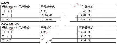
Advanced Channel Modeling: Because eight-antenna LTE systems use advanced antenna techniques, the modeled channels used in the tests must replicate the physical characteristics of the channels used in these techniques. If every detail is not included in the simulation, it is possible to establish an incorrect baseline that does not provide an assessment of the true system performance. For example, polarization affects the signal power received by the user device. The received signal appears to have lower power than the unpolarized case. This loss directly due to polarization depends on the orientation of the user device relative to the eNodeB antenna array. The
antenna pattern also has a direct impact on signal strength. The power of the received signal will vary depending on the direction of signal propagation. Since each possible scenario has a unique set of angles of separation (AoD), the power will again vary with direction. The problem becomes even more difficult when antenna pattern and polarization are combined. Table 1 shows the power loss for different combinations of dual channel scenarios. The “X” in the table represents a cross-polarized antenna pair, while the vertical bars (||) represent non-polarized antenna components.

Table 1: Effects of polarization and antenna pattern on received power.
Dynamic Scenarios: Testing a beamforming system under static (non-moving) conditions is not enough. Beamforming essentially consists of two steps: estimating the direction of the UE and pointing the beam in that direction. When the UE moves, its direction (relative to the eNodeB antenna array) also changes. This phenomenon raises two fundamental questions in understanding system performance: how fast can the system track the movement of the UE, and how does the system's performance suffer? To answer these questions, beamforming systems must be tested using dynamic scenarios that represent actual operating conditions. Test
Methodology
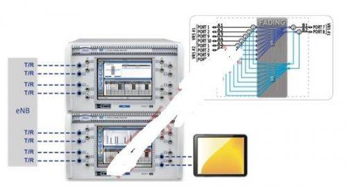
For the reasons discussed above, an effective test methodology must be able to address the challenges described: a large number of reciprocal RF channels in a compact size, channel modeling that takes into account antenna patterns and polarization, and the ability to test beamforming in dynamic (moving) scenarios. The number of channels required for bidirectional 8×N system testing presents unprecedented challenges. Figure 3 shows a modern system for 8×2 bidirectional testing. Traditional channel emulators may occupy a 40U rack and require a lot of external RF hardware to achieve the same channel scenario. [page]

Figure 3: Channel emulation for 8×2 MIMO beamforming testing.
As technology advances, the requirements placed on test systems will only become more challenging and demanding. One example is a dual-stream beamforming application, which involves two UEs talking to the same eNodeB BTS from different physical locations. The required test topology involves an 8×4 bidirectional MIMO channel (that is, 16 RF channels with 32 digital channels). Another example is IRC. Testing IRC requires the eNodeB BTS (the device under test (DUT) in this test case) to receive signals from a “desired” UE and multiple interfering UEs, and the test also takes into account the effects of fading.
As new technologies are developed and existing technologies are deployed in high-antenna-count MIMO systems, challenging test scenarios will emerge in the future. For example, multi-user MIMO (MU-MIMO) is not a new test, but testing it in the context of MIMO UEs in LTE presents some significant challenges because there are multiple complex technologies layered together in a “layered” manner. In MU-MIMO, signal processing is used to exploit the spatial differences between multiple UEs. Another example is coordinated multi-point (CoMP) transmission in LTE-A. This technology exploits network redundancy when UEs are connected to multiple eNodeB BTSs, typically at overlapping cell edges.
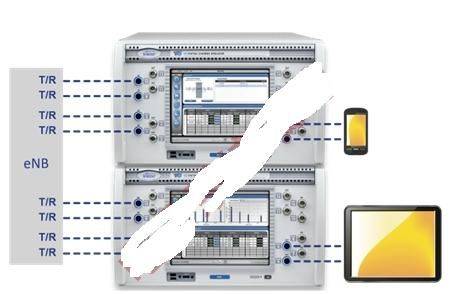
Figure 4 shows a typical compact setup for testing dual-stream beamforming, MU-MIMO, and CoMP with integrated bidirectional MIMO channels. The channel density of the integrated solution goes beyond the challenge of dealing with a large number of RF channels in a limited lab space. It is also a more stable platform in terms of calibration and stability.

Figure 4: This compact test setup handles dual-stream beamforming, MU-MIMO, and CoMP test scenarios.
Geometric Channel Models
When it comes to testing advanced antenna technologies for LTE and LTE-A systems, traditional MIMO channel modeling based on correlation matrices falls short. This traditional modeling approach does not capture the spatial characteristics of the MIMO channel or the effects of advanced antenna technologies discussed earlier.
Most correlation matrix-based MIMO channel modeling is based on the assumption that the signal is omnidirectional when it leaves the transmit antenna and that it arrives at the receive antenna in the same manner. This is not the case in MIMO beamforming.
To address this issue, the research community has proposed a new channel modeling approach, called geometric channel modeling (GCM). In GCM, each signal path from the transmit antenna to the receive antenna is geometrically traced and combined to form the channel. This approach inherently supports antenna patterns and polarizations. Due to these features, GCM has been chosen for evaluating next-generation wireless technologies.
Real-time fading
enables trial-and-error R&D troubleshooting. In dynamic or mobile scenarios, channel parameters change over time. Real-time fading allows developers to script channel parameters to mimic the channel dynamics. With the real-time fading engine, creating different types of UE movements for beamforming testing is very simple and intuitive.
R&D testing requires the flexibility to control the channel for troubleshooting. Coupled with geometric channel modeling, real-time fading allows engineers to adjust one or more channel parameters and get an immediate response. This “trial and error troubleshooting” approach is common in product development and has been widely used in various system performance tests.
As the industry drives higher data rates for newer wireless applications, the number of antennas used and the complexity of advanced antenna technologies will inevitably increase. This trend will pose a huge challenge to testing LTE and LTE-A with advanced antenna technologies. Therefore, new ways of thinking and approaches to test scenarios will be necessary. An
eight-antenna system can increase the number of RF channels used by a 2×2 MIMO system by four times, and researchers have begun to explore technologies that require eight times the number of antenna elements of a 2×2 system. If reproducing the reciprocal high-antenna count test scenario in the lab, there will be many serious constraints in terms of space and other resources. Compared with traditional channel modeling, emerging advanced antenna technologies bring another challenge. When testers need to fully understand system performance, testing the system in dynamic scenarios is essential.
An effective test method that can meet these challenges must use geometric channel modeling that can support a variety of advanced antenna technologies. It must also be able to run dynamic scenarios in real time. Finally, this test method must be able to reliably and efficiently create all the details of the bidirectional MIMO channel in an eight-antenna system and be able to do so in a compact form factor.
Previous article:Design of inter-cell mobile connection test for low-cost multi-mode LTE smartphones
Next article:Promoting WiMAX RF Testing and Characterization Based on ATE
- Popular Resources
- Popular amplifiers
- Keysight Technologies Helps Samsung Electronics Successfully Validate FiRa® 2.0 Safe Distance Measurement Test Case
- From probes to power supplies, Tektronix is leading the way in comprehensive innovation in power electronics testing
- Seizing the Opportunities in the Chinese Application Market: NI's Challenges and Answers
- Tektronix Launches Breakthrough Power Measurement Tools to Accelerate Innovation as Global Electrification Accelerates
- Not all oscilloscopes are created equal: Why ADCs and low noise floor matter
- Enable TekHSI high-speed interface function to accelerate the remote transmission of waveform data
- How to measure the quality of soft start thyristor
- How to use a multimeter to judge whether a soft starter is good or bad
- What are the advantages and disadvantages of non-contact temperature sensors?
- LED chemical incompatibility test to see which chemicals LEDs can be used with
- Application of ARM9 hardware coprocessor on WinCE embedded motherboard
- What are the key points for selecting rotor flowmeter?
- LM317 high power charger circuit
- A brief analysis of Embest's application and development of embedded medical devices
- Single-phase RC protection circuit
- stm32 PVD programmable voltage monitor
- Introduction and measurement of edge trigger and level trigger of 51 single chip microcomputer
- Improved design of Linux system software shell protection technology
- What to do if the ABB robot protection device stops
- Murata launches high-precision 6-axis inertial sensor for automobiles
- Ford patents pre-charge alarm to help save costs and respond to emergencies
- New real-time microcontroller system from Texas Instruments enables smarter processing in automotive and industrial applications
- Sandia Labs develops battery failure early warning technology to detect battery failures faster
- Ranking of installed capacity of smart driving suppliers from January to September 2024: Rise of independent manufacturers and strong growth of LiDAR market
- Industry first! Xiaopeng announces P7 car chip crowdfunding is completed: upgraded to Snapdragon 8295, fluency doubled
- P22-009_Butterfly E3106 Cord Board Solution
- Keysight Technologies Helps Samsung Electronics Successfully Validate FiRa® 2.0 Safe Distance Measurement Test Case
- Innovation is not limited to Meizhi, Welling will appear at the 2024 China Home Appliance Technology Conference
- Innovation is not limited to Meizhi, Welling will appear at the 2024 China Home Appliance Technology Conference
- Prize live broadcast: Registration for NXP's RT06F-based facial recognition technology solution is now open!
- Device thermal coupling and heat dissipation solutions on PCB
- Some considerations for DSP hardware design
- The significance of weld seam tracking sensors in the field of welding
- TI's new optical stage lighting DLP chipset is said to provide up to 15,000 lumens of monochrome light
- Memory alignment processing for ARM processors
- Last day for pre-registration! In-depth analysis of Infineon's star product IGBT7, live broadcast to understand the device operation and load process
- [Rawpixel RVB2601 development board trial experience] Use FreeRTOS with caution
- Brushless motor drive control hardware circuit sharing
- Share: [Skills Competition Notes 01] Zigbee point-to-point button control program development


 CDS1N5992AUR-1


 京公网安备 11010802033920号