1. Introduction
With the acceleration of the construction of digital substations and smart grids, electronic transformers have developed rapidly.
Electronic transformers include electronic current transformers and electronic voltage transformers. In order to ensure the accuracy of electronic transformers and ensure the safety and stability of the system, the transformers need to be calibrated. The electronic transformer calibration system is used to calibrate the ratio difference and angle difference of electronic transformers.
Compared with traditional transformers, electronic transformers have undergone fundamental changes in measurement principles, structures and output signal methods. Their calibration principles and methods are completely different from those of traditional transformers. Therefore, the calibration methods of traditional transformers cannot be applied to the calibration of electronic transformers.
LabVIEW is a graphical programming language (G language). Different from traditional text-based programming languages, it encapsulates various functions into function modules, can quickly establish a graphical user interface for the system, has the characteristics of high development efficiency and short development cycle, and is widely used in test measurement and signal processing. Programs written using the LabVIEW development environment are called virtual instrument programs (VI).
This paper establishes a calibration system for electronic transformers based on NI's PCI-4474 data acquisition board and LabVIEW development environment, and combines synchronous signal cards and digital signal processing to achieve transformer calibration. For calibrating electronic voltage transformers with voltage levels of 10~500kV and electronic current transformers with rated currents of 5~5000A, the accuracy can reach 5/10,000, with the characteristics of high accuracy, stable and reliable performance, and meets the requirements for the calibration of electronic transformer ratio and angle difference. Field tests have shown the effectiveness of the calibration system established in this paper.
2. System composition
The calibration system consists of hardware and software. The system hardware mainly includes the following parts:
(1) Standard voltage and current (electromagnetic) transformers (including boosters and current boosters). The purpose of using standard transformers is to provide standard output signals for the calibration system, and they must be traceable. The transformer accuracy is selected to be 0.01 level in order to improve the measurement accuracy of the system.
(2) PCI-4474 data acquisition board. This board is a dynamic signal acquisition card for high-precision dynamic and transient measurements. It has 4 synchronous sampling analog input channels with an input signal of -10~10VDC. In addition, it has 24-bit resolution and a maximum sampling rate of 102.4kS/s.
(3) Sampling resistor. Select a sampling resistor with a resistance of 80Ω and a rated current of 0.05A, with an accuracy of 100ppm.
(4) Voltage transformer 100V (100/√3V)/4V, with an accuracy of 0.01 level; current transformer 5A/0.05A, with an accuracy of 0.01 level.
(5) Synchronization card: used to synchronize the test transformer merging unit and the standard loop acquisition card.
(6) Merging unit: The main function of the merging unit is to synchronously receive the digital signals output by 12 electronic transformers (the 12 signals are defined in accordance with the DATASET data channel specified in the IEC60044-8 standard), and send them to the relay protection, measurement and control equipment in accordance with the frame format specified in the IEC60044-8 standard.
The merging unit generally provides a total of 12 current and voltage signals (all optical fiber transmission), including 7 current signals and 5 voltage signals, which are packaged according to certain rules and output through Ethernet. The merging unit is generally provided by the user and complies with the GBT-20840-7/8 and IEC61580-9 standards.
The connection between the merging unit and the verification system mainly includes two parts: one is the synchronous pulse signal connection, and the other is the Ethernet connection. The connection block diagram of the merging unit and the verification system is shown in Figure 1:

(7) Industrial computer. The industrial computer is connected to the standard A/D converter through a PCI-GPIB card with a communication protocol of IEEE488.2.
(8) Voltage regulator.
The system software is the LabVIEW development environment, which consists of three parts: front panel, block diagram program, and icon/connector.
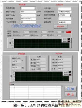
(1) The front panel is the graphical user interface of LabVIEW, which can monitor various parameters in the system. It consists of input controls and display controls, as shown in Figure 4.
(2) The block diagram program is written in a graphical programming language, which is equivalent to the program statements of a text-based programming language and can achieve specific functions.
(3) The icon/connector can generate a subVI for other VIs to call from the program (VI) written in the LabVIEW development environment, which improves the readability and development efficiency of the program.
3. Principle of the verification system The
working principle of this verification system can be divided into two parts: the electronic current transformer verification principle and the electronic voltage transformer verification principle.
3.1 Principle of electronic current transformer verification The
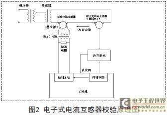
standard electromagnetic current transformer is connected in series with the electronic current transformer under test. The current booster provides current to the primary side of the transformer, and the voltage regulator is adjusted to change the output current of the current booster. The secondary side of the standard CT is connected to the standard current transformer 5A/0.05A, and its secondary side is connected to the standard resistor. The voltage on the resistor is taken and input into the data acquisition card (PCI-4474). The current signal obtained from the secondary side of the electronic current transformer is sent to the merging unit on the low-voltage side by optical fiber. The computer obtains the measurement results of the standard CT through the data acquisition card and the measurement results of the electronic current transformer through Ethernet. The electronic current transformer under test and the data acquisition card are synchronously sampled by calculation and providing clock synchronization signals.
After digital filtering, DFT operation and other signal results, the ratio error and phase error of the electronic current transformer are calculated.
The verification principle is shown in Figure 2.

3.2 Electronic voltage transformer calibration principle The
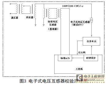
electronic voltage transformer calibration principle is similar to the electronic current transformer calibration principle. The difference is that the standard electromagnetic voltage transformer is connected in parallel with the primary side of the electronic voltage transformer under test. The booster provides voltage to the primary side of the transformer, and the output voltage is adjusted by the voltage regulator. The secondary side of the standard PT is connected to the standard voltage transformer 100V (100/√3V)/4V and input into the data acquisition card (PCI-4474). The principle is shown in Figure 3. [page]

4. System features and performance indicators
This calibration device is suitable for laboratory and on-site accuracy calibration of electronic transformers that comply with the IEC61850-(9-1, 9-2) standard digital output and IEC60044-7/8 standard output.
4.1 System features
(1) Users do not need to understand IEC61850 or IEC60044-8, nor do they need to set a MAC address to calibrate transformer errors.
(2) Calibrate non-traditional transformers (small signal output).
(3) Built-in 4-channel 24-Bit sigma-delta AD meets the large amount of computing and other various needs that may arise in the future.
(4) Can be traced back using an 8.5-digit high-precision digital multimeter (Agilent3458A).
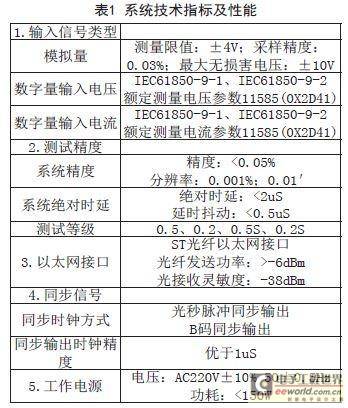
4.2 Technical indicators and performance (as shown in Table 1)

5. Design of the calibration system interface based on LabVIEW
This calibration system is designed based on the LabVIEW8.6 development environment. The software interface includes three parts: system calibration interface, detailed parameter analysis interface and system verification interface.
The system verification interface mainly displays the statistical results after completing the software calculation, as shown in Figure 4. This interface is the core of the entire system. After the parameter configuration is completed, click the start button. The system completes the entire inspection and detection in a "one-click" manner according to the configuration parameters, and can display the standard source amplitude percentage, system rate, ratio difference (maximum value, minimum value and average value), phase difference, maximum value, minimum value and average value, and detailed parameter table for each comparison (number of comparisons, amplitude percentage, ratio difference, angle difference, phase difference and whether the data of this comparison is self-valid, etc.).

6. Conclusion
This paper aims at the working principle and composition structure of electronic transformer, and establishes a transformer calibration system based on NI data acquisition board and LabVIEW development environment. It has the characteristics of high measurement accuracy and simple operation, and has certain practical value.
Previous article:Design of HDTV Main Control Board Automatic Test System Based on LabVIEW
Next article:Multi-sensor air flow test system solution
Recommended ReadingLatest update time:2024-11-16 14:45


![[]LabVIEW Application-SubVI Call](https://6.eewimg.cn/news/statics/images/loading.gif)


- Popular Resources
- Popular amplifiers
-
 100 Examples of Microcontroller C Language Applications (with CD-ROM, 3rd Edition) (Wang Huiliang, Wang Dongfeng, Dong Guanqiang)
 -
 Arduino Nano collects temperature and humidity data through LabVIEW and DHT11
 -
 Modern Testing Technology and System Integration (Liu Junhua)
 -
 Computer Control System Analysis, Design and Implementation Technology (Edited by Li Dongsheng, Zhu Wenxing, Gao Rui)
- Keysight Technologies Helps Samsung Electronics Successfully Validate FiRa® 2.0 Safe Distance Measurement Test Case
- From probes to power supplies, Tektronix is leading the way in comprehensive innovation in power electronics testing
- Seizing the Opportunities in the Chinese Application Market: NI's Challenges and Answers
- Tektronix Launches Breakthrough Power Measurement Tools to Accelerate Innovation as Global Electrification Accelerates
- Not all oscilloscopes are created equal: Why ADCs and low noise floor matter
- Enable TekHSI high-speed interface function to accelerate the remote transmission of waveform data
- How to measure the quality of soft start thyristor
- How to use a multimeter to judge whether a soft starter is good or bad
- What are the advantages and disadvantages of non-contact temperature sensors?
- Innolux's intelligent steer-by-wire solution makes cars smarter and safer
- 8051 MCU - Parity Check
- How to efficiently balance the sensitivity of tactile sensing interfaces
- What should I do if the servo motor shakes? What causes the servo motor to shake quickly?
- 【Brushless Motor】Analysis of three-phase BLDC motor and sharing of two popular development boards
- Midea Industrial Technology's subsidiaries Clou Electronics and Hekang New Energy jointly appeared at the Munich Battery Energy Storage Exhibition and Solar Energy Exhibition
- Guoxin Sichen | Application of ferroelectric memory PB85RS2MC in power battery management, with a capacity of 2M
- Analysis of common faults of frequency converter
- In a head-on competition with Qualcomm, what kind of cockpit products has Intel come up with?
- Dalian Rongke's all-vanadium liquid flow battery energy storage equipment industrialization project has entered the sprint stage before production
- Allegro MicroSystems Introduces Advanced Magnetic and Inductive Position Sensing Solutions at Electronica 2024
- Car key in the left hand, liveness detection radar in the right hand, UWB is imperative for cars!
- After a decade of rapid development, domestic CIS has entered the market
- Aegis Dagger Battery + Thor EM-i Super Hybrid, Geely New Energy has thrown out two "king bombs"
- A brief discussion on functional safety - fault, error, and failure
- In the smart car 2.0 cycle, these core industry chains are facing major opportunities!
- The United States and Japan are developing new batteries. CATL faces challenges? How should China's new energy battery industry respond?
- Murata launches high-precision 6-axis inertial sensor for automobiles
- Ford patents pre-charge alarm to help save costs and respond to emergencies
- New real-time microcontroller system from Texas Instruments enables smarter processing in automotive and industrial applications
- The dynamic diagram explains the lead and lag of voltage and current
- Parallel switch type voltage regulator circuit
- Can STM32 USB AUDIO realize recording?
- EEWORLD University - From entry to mastery of Huawei IoT technology
- A First Look at TouchGFX
- 【mpy】STM32 supports using HSI as the main clock
- dsp bootloader c5000
- Highlight Review丨What hard-core technologies did ADI demonstrate at IMS 2019?
- Wenqiao
- The SIN-IMX6UL development board transfers files to the development board via USB HOST

 100 Examples of Microcontroller C Language Applications (with CD-ROM, 3rd Edition) (Wang Huiliang, Wang Dongfeng, Dong Guanqiang)
 Arduino Nano collects temperature and humidity data through LabVIEW and DHT11


 京公网安备 11010802033920号