The most common type of traditional CMM is the trigger probe. When measuring an object with a trigger probe, the probe contacts the surface of the object at a certain speed, causing the position of the probe to deviate. The generated electrical signal triggers the probe to record the spatial coordinates of a point on the surface of the object. The first problem caused by this is the slow measurement speed. The reason is that the point sampling method of the trigger probe is discontinuous. After completing one point sampling, the probe needs to retreat a certain distance to allow the probe to return to its position before the second point sampling can be performed. In addition, the speed of contacting the surface of the object when sampling cannot be too fast. If the probe contacts the object too fast and the position of the probe deviates too much, the signal will be considered to have collided and the point sampling fails. For this reason, a scanning probe can be used instead of a trigger probe. The scanning probe adopts a continuous point sampling method, so the point sampling speed is greatly improved. The second reason for limiting the measurement speed is that if the object to be measured has a relatively complex geometric shape, the probe needs to change its direction several times to complete the entire measurement, and each direction of the probe needs to be calibrated. If we want to overcome this shortcoming and further improve the measurement speed, we need to equip the three-dimensional coordinate measuring machine with a high-end multi-axis rotary scanning probe. This new technology can scan objects at high speed in a continuous manner to collect points.
The tip of the stylus used in contact measurement is generally a ruby ball, and the spatial coordinates obtained by the probe sampling point are the center position of the ruby ball. However, the actual contact position between the stylus and the surface of the object is not the center of the ball, so the coordinates of the object point must be compensated according to the radius of the ruby ball. This brings up the second problem of contact measurement, that is, the radius compensation direction of the ruby ball is wrong. When the measured geometric feature is small (diameter < 1mm) and the sampling density is high, the order of the points collected will be confused, resulting in errors in the ball radius compensation direction, causing the obtained geometric features to be inconsistent with the actual ones (Figure 1).
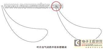
Figure 1 Radius compensation error of the blade outlet edge
In addition, since there is a certain degree of unevenness on the surface of the object and the diameter of the ruby ball is much larger than the surface unevenness, the stylus cannot measure the tiny depressions on the surface of the object (Figure 2).
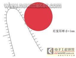
Figure 2: The ruby ball stylus cannot detect tiny depressions on the surface of an object
The third problem with contact measurement is the surface characteristics of the object being measured. If the surface of the object being measured is relatively soft, delicate, or easily damaged, it is not suitable to use a contact probe. When the probe contacts the surface of the object, it may deform it at best, resulting in a large error; at worst, it may damage the surface of the object.
For the above reasons, optical measurement has an essential advantage over it. As a non-contact measurement method, optical measurement does not use a contact probe to take points, but uses certain characteristics of light to measure. This completely avoids the potential problems caused by ruby ball compensation, and also makes the surface of the measured object no longer affected by the contact of the probe. As for the measurement speed, it depends on the type of optical probe. But no matter which probe is used, its point-taking method is continuous. Moreover, during the point-taking process, the optical probe is different from the contact probe. The contact probe will be considered to have collided because of the high speed when contacting the surface of the object. Since the optical probe does not encounter this problem at all, the point-taking speed is further improved.
There are many ways to classify optical probes, and the types are even more complicated. From the measurement principle, it can usually be divided into coaxial measurement and triangulation; from the light source properties, it can be divided into active light source and passive light source; from the light source dimension, it can be divided into point light source, line light source and surface light source; from the light source color spectrum, it can be monochromatic light source and white light source. There are two common methods in coaxial measurement. One is the interference method, which uses the wavelength characteristics of light to divide a beam of light into two beams through a plane beam splitter (semi-transparent and semi-reflective). One beam is reflected by the mirror to the reference plane, and the other beam is transmitted to the surface of the object to be measured. After the two beams of light are superimposed, interference fringes are generated. The form of the interference fringes depends on the distance of the object and the geometric characteristics of the object surface. The other is the confocal method. The detection light emitted from a point light source is focused on the object to be measured through a lens. If the object is exactly at the focus, the reflected light should converge back to the light source through the original lens. This is called confocal. A half-reflective and half-mirror is added to the optical path of the reflected light to bend the reflected light to a baffle with a small hole. The position of the small hole is equivalent to the light source. The photometer measures the intensity of the reflected light at the pinhole. When the intensity is the largest, the object is located at the focal plane of the lens, so the position of the object point can be measured. Triangulation uses the triangular relationship between the light source, the image point, and the object point to find the distance of the object point. Let's take a point light source as an example (Figure 3):
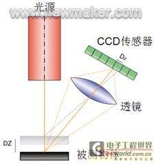
Figure 3 Schematic diagram of triangulation
The light source emits a light point to the object. After the light point reaches the object, it is reflected on the sensor to obtain an image point. The light source, object point and image point form a certain triangular relationship. The position of the light source and the image point on the sensor is known, so the position of the object point can be calculated. Some probes use line light sources instead of point light sources, projecting a light stripe composed of several light points onto the surface of the object (Figure 4). What is received on the sensor is a two-dimensional distorted light image. The distorted shape of the light depends on the position of each object point. Such a line light source probe can greatly increase the speed of point sampling. [page]

Figure 4 Projecting a light stripe consisting of several light spots onto the surface of an object
Some probes even use gratings to disperse and encode a beam of light to form a structured light source with a certain pattern. In this way, a set of distorted light rays can be obtained on the sensor, thereby further improving the speed of point acquisition (Figure 5).
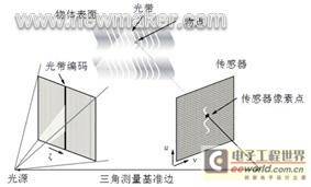
Figure 5 The probe uses a grating to disperse and encode a beam of light to form a structured light source with a certain pattern.
At present, the types of light sources used by various optical probes are mainly laser and white light. Laser, as a collimated, coherent monochromatic light, is widely used as the light source of point probes and line probes. White light is composed of light of various wavelengths, so it is white in color and is currently used more as a structured light source. Due to the physical properties of white light, white light point probes are gradually being used in the field of measurement. The biggest difference between laser and white light is that laser is a monochromatic light, so it has a high degree of coherence. Some probes use the coherence of laser to achieve their functions; while white light is composed of light of various wavelengths, so the coherence is quite weak. As mentioned earlier, the high coherence of monochromatic light can be used for measurement according to certain principles, but the two sides of things also show that coherence can interfere with measurement in some places. For example, when a laser probe uses the reflected light from the surface of an object for triangulation measurement, the laser irradiated to the surface of the object will present a granular structure. This granular structure is called "speckle", and this phenomenon is called "speckle effect". The speckle effect is caused by the reflection of the laser on the rough surface. The surfaces of most objects are rough compared to the wavelength of the laser. Therefore, when the light wave is reflected from the surface of the object, each point on the surface emits a beam of highly coherent sub-waves. The superposition of the sub-waves results in the formation of randomly distributed speckles on the surface of the object (Figure 6).
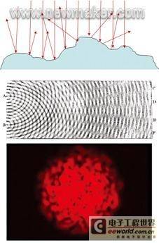
Figure 6 The result of wavelet superposition is the randomly distributed speckle on the surface of the object.
Since white light is composed of light of various wavelengths, its coherence is greatly weakened, so it is difficult to observe the speckle effect when it is reflected on the surface of an object. This difference has a huge impact on triangulation. The reason is that triangulation relies on the position of the image point on the sensor to determine the spatial position of the object point. The image point on the sensor is usually not a simple point. The reflected light shines on the sensor to make a part of the pixels sensitive. The computer can determine the center of this group of pixels through pixel analysis to obtain the position of the image point. Due to the existence of the speckle effect, it becomes very difficult to determine the position of the image point, and the error is large. The light points that are evenly distributed and symmetrical are very beneficial to the determination of the image point position (Figure 7). This is the fundamental reason why white light performs better than laser in triangulation.
Previous article:How to do a simple gas chromatography configuration
Next article:Laser tracker solves the measurement problem of large workpieces
- Popular Resources
- Popular amplifiers
- New IsoVu™ Isolated Current Probes: Bringing a New Dimension to Current Measurements
- Modern manufacturing strategies drive continuous improvement in ICT online testing
- Methods for Correlation of Contact and Non-Contact Measurements
- Keysight Technologies Helps Samsung Electronics Successfully Validate FiRa® 2.0 Safe Distance Measurement Test Case
- From probes to power supplies, Tektronix is leading the way in comprehensive innovation in power electronics testing
- Seizing the Opportunities in the Chinese Application Market: NI's Challenges and Answers
- Tektronix Launches Breakthrough Power Measurement Tools to Accelerate Innovation as Global Electrification Accelerates
- Not all oscilloscopes are created equal: Why ADCs and low noise floor matter
- Enable TekHSI high-speed interface function to accelerate the remote transmission of waveform data
- Intel promotes AI with multi-dimensional efforts in technology, application, and ecology
- ChinaJoy Qualcomm Snapdragon Theme Pavilion takes you to experience the new changes in digital entertainment in the 5G era
- Infineon's latest generation IGBT technology platform enables precise control of speed and position
- Two test methods for LED lighting life
- Don't Let Lightning Induced Surges Scare You
- Application of brushless motor controller ML4425/4426
- Easy identification of LED power supply quality
- World's first integrated photovoltaic solar system completed in Israel
- Sliding window mean filter for avr microcontroller AD conversion
- What does call mean in the detailed explanation of ABB robot programming instructions?
- 2024 China Automotive Charging and Battery Swapping Ecosystem Conference held in Taiyuan
- State-owned enterprises team up to invest in solid-state battery giant
- The evolution of electronic and electrical architecture is accelerating
- The first! National Automotive Chip Quality Inspection Center established
- BYD releases self-developed automotive chip using 4nm process, with a running score of up to 1.15 million
- GEODNET launches GEO-PULSE, a car GPS navigation device
- Should Chinese car companies develop their own high-computing chips?
- Infineon and Siemens combine embedded automotive software platform with microcontrollers to provide the necessary functions for next-generation SDVs
- Continental launches invisible biometric sensor display to monitor passengers' vital signs
- Another technical solution for power-type plug-in hybrid: A brief discussion on Volvo T8 plug-in hybrid technology
- If the mobile phone signal strength is -90dbm (medium strength), the conversion success rate = 10^-6mw (is the calculation correct?)
- Has Jialichuang started to use routine marketing?
- GaN technology detailed explanation is here
- How to tell if an EEPROM chip is bad?
- New pyESP32 development board
- Developing ST BlueNRG-LP projects using Visual Studio
- MSP430 IO and internal structure diagram
- 89c51 and USB flash drive
- Power Engineer's Handbook - Collection of Various Filter Circuits 2
- [RVB2601 Creative Application Development] 3 Light up the screen to display the letter A

 TL071MFK/883B


 京公网安备 11010802033920号