Overview
For decades, electrical sensors have been used as standard equipment for measuring physical and mechanical phenomena. Although they are ubiquitous in test and measurement, as electrical devices, they have inherent defects, such as signal loss during transmission and susceptibility to electromagnetic noise. These defects make the use of electrical sensors quite challenging or even completely unsuitable in some special applications. Fiber optic sensors are an excellent solution to these application challenges, using light beams instead of current and standard optical fibers instead of copper wires as the transmission medium.
In the past two decades, the development of optoelectronics and a large number of innovations in the fiber optic communication industry have greatly reduced the price and improved the quality of optical devices. By adjusting the economic scale of the optical device industry, fiber optic sensors and fiber optic instruments have expanded from the laboratory experimental research stage to practical field applications, such as building structural health monitoring applications.

Figure 1. Cross-section of a typical optical fiber.
Fiber Bragg Grating (FBS) Sensors
Fiber Bragg grating sensor is the most frequently used and widely used fiber optic sensor. This sensor can change the wavelength of the reflected light wave according to the change of ambient temperature and/or strain. Fiber Bragg grating is to expose a short section of light-sensitive optical fiber to a light wave with a periodic distribution of light intensity through holographic interferometry or phase mask method. In this way, the refractive index of the optical fiber will change permanently according to the intensity of the light wave it is exposed to. The periodic change of the refractive index of light caused by this method is called fiber Bragg grating.
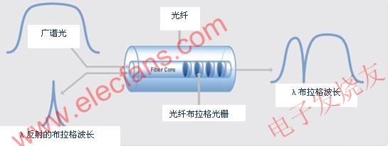
When a broad spectrum light beam is transmitted to a fiber Bragg grating, each small section of the optical fiber after the refractive index is changed will only reflect a specific wavelength of light, which is called the Bragg wavelength, as shown in the following equation (1). This characteristic makes the fiber Bragg grating reflect only a specific wavelength of light, while other wavelengths of light are transmitted.
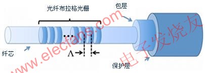
In equation (1), λb is the Bragg wavelength, n is the effective refractive index of the fiber core, and Λ is the spacing length between the gratings, called the grating period.

Figure 2. Working principle of fiber Bragg grating sensor
Because the Bragg wavelength is a function of the spacing length between gratings (Λ in equation (1)), fiber Bragg gratings can be produced with different Bragg wavelengths, so that different fiber Bragg gratings can be used to reflect light waves of specific wavelengths.

Figure 3. Fiber Bragg Grating perspective view
Changes in strain and temperature will affect the effective refractive index n and grating period Λ of the fiber Bragg grating at the same time, resulting in a change in the wavelength of the light wave reflected by the grating. The change in the reflected wavelength of the fiber Bragg grating with strain and temperature can be approximately expressed by the relationship in equation (2):
Where Δλ is the change in reflected wavelength and λo is the initial reflected wavelength.
The first expression before the plus sign on the right shows the effect of strain change on the reflected wavelength. Where pe is the strain optical sensitivity coefficient and ε is the strain effect on the grating. The second expression after the plus sign shows the effect of temperature change on the wavelength. Where αΛ is the thermal expansion coefficient and αn is the temperature optical sensitivity coefficient. αn reflects the effect of light refractive index due to temperature change and αΛ reflects the change of grating period caused by the same temperature change.
Because the Fiber Bragg Grating is affected by both strain and temperature changes, both factors must be considered simultaneously and analyzed separately when calculating the change in reflected wavelength. When measuring temperature, the Fiber Bragg Grating must be kept completely unaffected by strain. You can use a FBG temperature sensor that is packaged specifically for this purpose, which ensures that the properties of the Fiber Bragg Grating inside the package are not coupled to any external bending, stretching, squeezing or twisting strain. In this case, the thermal expansion coefficient of the glass αΛ is usually negligible in practical use; therefore, the change in reflected wavelength caused by temperature changes can be mainly determined by the temperature optical sensitivity coefficient αn of the fiber.
Fiber Bragg grating strain sensors are somewhat more complex because both temperature and strain affect the sensor's reflected wavelength. In order to perform the measurement correctly, the temperature effect on the fiber Bragg grating must be compensated during the test. To achieve this compensation, an FBG temperature sensor that has good thermal contact with the FBG strain sensor can be used. After obtaining the test results, simply subtract the wavelength change measured by the FBG temperature sensor from the wavelength change measured by the FBG strain sensor to eliminate the second expression on the right side of the plus sign from equation (2), thus compensating for the effect of temperature changes in the strain test.
The process of installing a fiber Bragg grating strain sensor is similar to that of installing a traditional electrical strain sensor, and there are many different types and mounting methods of FBG strain sensors to choose from, including epoxy, weldable, bolt-on, and embedded types.
Inquiry Method
Since fiber Bragg gratings can be implanted with different specific reflection wavelengths, they can be used to implement good wavelength division multiplexing (WDM) technology. This feature makes it possible to connect multiple sensors with specific Bragg wavelengths in a daisy chain on a long independent optical fiber. Wavelength division multiplexing technology assigns a specific wavelength range to each FBG sensor in the available optical spectrum for use. Due to the inherent wavelength characteristics of fiber Bragg gratings, even if the light intensity is lost and attenuated due to the bending and transmission of the optical fiber medium during the transmission process, the results measured by the sensor can still remain accurate.
The operating wavelength range of each individual fiber Bragg grating sensor and the total wavelength range that can be interrogated by the wavelength interrogator determine the number of sensors that can be connected to a single optical fiber. Generally speaking, because the wavelength change caused by strain changes is more significant than the wavelength change caused by temperature changes, the FBG strain sensor is generally assigned an operating wavelength range of about 5 nanometers, while the FBG temperature sensor is assigned an operating wavelength range of about 1 nanometer. Because the test range provided by the conventional wavelength interrogator is about 60 to 80 nanometers, the number of sensors connected to a single optical fiber can generally range from 1 to 80 - of course, this is based on the fact that the reflection wavelength regions of each sensor do not overlap in the spectral range (Figure 4). Therefore, when selecting FBG sensors, it is necessary to carefully select the nominal wavelength and operating wavelength range to ensure that each sensor has its own independent operating wavelength region.

Figure 4. Each FBG sensor connected to the same optical fiber must have its own independent operating wavelength range.
Typical FBG sensors have an operating wavelength range of a few nanometers, so the optical interrogator must be able to make measurements with a resolution of a few picometers or less - a fairly small order of magnitude. There are several ways to interrogate FBG grating sensors. Interferometers are commonly used laboratory devices that can provide fairly high-resolution spectral analysis. However, these instruments are generally very expensive, bulky and not rugged enough to be used in applications involving field monitoring of various structures such as wind turbine blades, bridges, water pipes and dams.
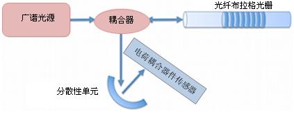
A more robust approach is to introduce a charge-coupled device (CCD) and a fixed dispersion unit, generally a wavelength position converter.
In this method, a broad spectrum light source is used to illuminate the FBG sensor (or a series of FBG sensors). These reflected light beams pass through a dispersive unit, which distributes the reflected light beams of different wavelengths to different locations on the surface of the charge coupled device (CCD), as shown in Figure 5 below.

Figure 5. Interrogation of FBG optical sensors using wavelength position conversion
This method can quickly and simultaneously measure all FBG sensors attached to the fiber, but it only provides very limited resolution and signal-to-noise ratio (SNR). For example, if we want to achieve a resolution of 1 picometer in the 80 nm wavelength range, we need a linear CCD device with 80,000 pixels, which is more than 10 times higher than the best linear CCD device currently available on the market (as of July 2010). In addition, because the energy of the broad-spectrum light source is dispersed over a wide wavelength range, the energy of the FBG reflected beam will be very small, which sometimes even makes it difficult to measure.
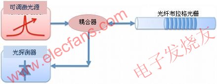
The most popular approach is to use a tunable Fabry-Perot filter to create a high-energy, rapidly scanned laser source to replace the traditional broad-spectrum light source. The tunable laser source concentrates the energy in a very narrow wavelength range, providing a high-energy light source with a high signal-to-noise ratio. The high optical power provided by this architecture makes it possible to use a single optical fiber to carry multiple optical channels, which can effectively reduce the cost of multi-channel interrogators and reduce the complexity of the system. The interrogator based on this tunable laser architecture can scan in a relatively large wavelength range with a very narrow spectral band. On the other hand, a photodetector will synchronize with this scan and measure the laser beam reflected from the FBG sensor. When the laser wavelength emitted by the tunable laser matches the Bragg wavelength of the FBG sensor, the photodetector can measure the corresponding response. When this response occurs, the wavelength of the tunable laser corresponds to the temperature and/or strain measured at the FBG sensor at that time, as shown in Figure 6.

Figure 6. Interrogation of FBG optical sensor using tunable laser source method
This method can achieve an accuracy of about 1 picometer, which corresponds to the accuracy of a traditional FBG sensor of about 1.2 microstrain (FBG strain sensor) or about 0.1 degrees Celsius (FBG temperature sensor). Because the tunable laser source method has a high optical power compared to other methods, this interrogation method can also be applied to measurement applications with longer fiber lengths (over 10 kilometers).
Advantages of FBG optical sensors
By using light waves instead of electric current and standard optical fiber instead of copper wire as the transmission medium, FBG optical sensing solves many challenges and difficulties faced by using electrical sensing. Both optical fiber and FBG optical sensors are insulators, have passive electrical properties, and are not affected by electromagnetic induction noise. Interrogators with high optical power adjustable laser sources can complete long-distance measurements with very low data loss rates or even zero data loss. At the same time, unlike electrical sensor systems, one optical channel can complete the test of multiple FBG sensors at the same time, greatly reducing the size, weight and complexity of the test system.
Optical sensors are an ideal solution for applications where common electrical sensors, such as foil strain gauges, thermocouples, and vibrating wire sensors, are difficult to use or even fail in harsh environments. Because the use and installation of optical sensors are similar to those of traditional electrical sensors, it is relatively simple to transition from electrical to optical testing solutions. Having a good understanding of how optical fiber and FBGs work will help you better embrace optical testing technology and harness all the advantages that this new technology brings.
Previous article:
Next article:A CMOS Image Sensor Based on Charge Pump
- Melexis launches ultra-low power automotive contactless micro-power switch chip
- Infineon's PASCO2V15 XENSIV PAS CO2 5V Sensor Now Available at Mouser for Accurate CO2 Level Measurement
- Milestone! SmartSens CMOS image sensor chip shipments exceed 100 million units in a single month!
- Taishi Micro released the ultra-high integration automotive touch chip TCAE10
- The first of its kind in the world: a high-spectral real-time imaging device with 100 channels and 1 million pixels independently developed by Chinese scientists
- Melexis Launches Breakthrough Arcminaxis™ Position Sensing Technology and Products for Robotic Joints
- ams and OSRAM held a roundtable forum at the China Development Center: Close to local customer needs, leading the new direction of the intelligent era
- Optimizing Vision System Power Consumption Using Wake-on-Motion
- Infineon Technologies Expands Leading REAL3™ Time-of-Flight Portfolio with New Automotive-Qualified Laser Driver IC
- Innolux's intelligent steer-by-wire solution makes cars smarter and safer
- 8051 MCU - Parity Check
- How to efficiently balance the sensitivity of tactile sensing interfaces
- What should I do if the servo motor shakes? What causes the servo motor to shake quickly?
- 【Brushless Motor】Analysis of three-phase BLDC motor and sharing of two popular development boards
- Midea Industrial Technology's subsidiaries Clou Electronics and Hekang New Energy jointly appeared at the Munich Battery Energy Storage Exhibition and Solar Energy Exhibition
- Guoxin Sichen | Application of ferroelectric memory PB85RS2MC in power battery management, with a capacity of 2M
- Analysis of common faults of frequency converter
- In a head-on competition with Qualcomm, what kind of cockpit products has Intel come up with?
- Dalian Rongke's all-vanadium liquid flow battery energy storage equipment industrialization project has entered the sprint stage before production
- Allegro MicroSystems Introduces Advanced Magnetic and Inductive Position Sensing Solutions at Electronica 2024
- Car key in the left hand, liveness detection radar in the right hand, UWB is imperative for cars!
- After a decade of rapid development, domestic CIS has entered the market
- Aegis Dagger Battery + Thor EM-i Super Hybrid, Geely New Energy has thrown out two "king bombs"
- A brief discussion on functional safety - fault, error, and failure
- In the smart car 2.0 cycle, these core industry chains are facing major opportunities!
- Rambus Launches Industry's First HBM 4 Controller IP: What Are the Technical Details Behind It?
- The United States and Japan are developing new batteries. CATL faces challenges? How should China's new energy battery industry respond?
- Murata launches high-precision 6-axis inertial sensor for automobiles
- Ford patents pre-charge alarm to help save costs and respond to emergencies
- Several TMS320C2X/C5X C language program development examples
- Starting from an annual salary of 200,000 yuan, are the salaries in the chip industry so high?
- EEWORLD University - Texas Instruments Deep Learning (TIDL) Overview
- Can the transmission speed of Zigbee be achieved on a small car?
- How to read and write CSRs of RISC-V processors using J-Link and Embedded Studio?
- Oscilloscope probe problems
- Applying Over-the-Air Firmware Upgrades to MSP 430 Microcontrollers
- Seeking help for the solution of the platform on the rising edge of BUCK type DCDC
- Please help me, teachers, the communication problem.
- Some notes on 28335 performance testing

 Fiber-Optic Communication Systems(Fourth Edition)


 京公网安备 11010802033920号