How to improve the battery energy efficiency ratio of IoT devices by extending life and reducing weight
In a world where everything is connected, IoT plays a vital role by connecting different sensor nodes to transmit data to secure servers. Power management is one of the key links to improve the efficiency of IoT applications.
In most applications, sensor nodes (data acquisition elements) are battery powered and placed in remote areas. Among them, the battery life depends on the efficiency of the power supply strategy in the sensor node design. Usually, sensor nodes are in sleep mode and only switch to active mode when data acquisition is performed. Therefore, the duty cycle of these devices is very low. In order to extend the battery life as much as possible, it is necessary to improve the performance of sleep current in IoT applications.
Power Management in IoT Devices
In a typical IoT system (as shown in Figure 1), wireless sensor nodes are mostly powered by batteries, so they are limited by battery life. Power management plays a key role in extending the use time of sensor nodes. When considering how to save power in sensor nodes, the concept of duty cycle is usually involved.
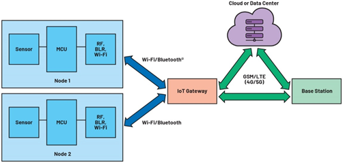
Figure 1. Typical building blocks of an IoT system
Since crosstalk and idle listening are the main sources of energy waste in sensor nodes, the power consumption of wireless sensor nodes can be evaluated from the following three different aspects:
►Sensors
►Microcontroller
►Radio Operation
The sensor collects raw data such as temperature and humidity and sends it to the microcontroller. The microcontroller is responsible for processing the raw data and transmitting it to the cloud or data center through a wireless link. However, since typical sensor applications run at a very low duty cycle (ranging from 0.01% to 1%) and are idle most of the time, a power management solution that uses a sensor node with very low sleep current will help extend battery life.
An example of such an application is a smart irrigation system, where sensor nodes measure soil moisture and collect data only once an hour.
What are the key functions of shipping mode and hibernation mode?
Ship mode and sleep mode are commonly used terms in battery-powered IoT devices and are key factors that need to be considered in power management in IoT applications.
Ship mode is a nanopower state that extends battery life during the product shipping phase. In Ship mode, the battery is disconnected from the rest of the system to minimize power consumption when the product is idle or not in use. Ship mode can be released with a button to resume normal operation of the device.
When the device is active, sleep mode can be used to extend battery life. In sleep mode, all system peripherals are either turned off or run at minimum power requirements. IoT devices will wake up periodically, perform specific tasks, and then go back to sleep mode.
Different sleep modes can be achieved by disabling various peripherals of the wireless sensor node. For example, in modem sleep mode, only the communication module is disabled. In light sleep mode, most modules are disabled (including communication module, sensor module, digital module, etc.), and in deep sleep mode, the power of the wireless sensor node is completely turned off.
Enabling deep sleep mode in sensor nodes can maximize battery life; therefore, optimizing deep sleep current is the only way to improve overall battery life.
Duty Cycling Methods to Enable Deep Sleep Mode in IoT Applications
Duty cycling in IoT modules is one of the common methods to enable deep sleep mode. When a wireless sensor node is in deep sleep, most peripherals are in power-off or shutdown mode, which consumes only a few nanoamps of current. A timing device such as a real-time clock (RTC) wakes up the IoT module after a programmed timeout period.
If this approach is used, the microcontroller is completely shut down when the system is in deep sleep mode. However, after resuming, there is always a startup time involved, which will add unnecessary latency. Given these trade-offs, the effectiveness of the proposed approach depends on the characteristics of each node and the duty cycle of the application.
Traditional Solution for Deep Sleep Mode and Ship Mode: Using RTC, Load Switch, and Push Button Controller
Traditional solutions usually use a load switch and RTC to switch the power of the wireless sensor node on/off. With this approach, only the load switch and RTC are active, reducing the total quiescent current to nanoamps.
The sleep time can be programmed by the microcontroller inside the wireless sensor node. An external push button controller can be connected to the load switch to enable the shipping mode function. The external push button is used to exit the shipping mode and put the wireless sensor node into normal operation mode.

Figure 2. Discrete solution block diagram
Deep Sleep and Transport Mode Improvements
The MAX16163/MAX16164 are nanopower controllers from Analog Devices that feature an on/off controller and programmable sleep time. The device integrates a power switch to enable the output and can provide up to 200mA of load current. The MAX16162/MAX16163 replaces traditional load switches, RTCs, and battery "freshness" ICs to reduce the number of bill of materials (BOM) and reduce costs. The wireless sensor node unit is connected to the battery through the MAX16162/MAX16163. The sleep time can be programmed by the microcontroller, or it can be set using an external resistor between PB/SLP and ground or using an I2C command from the microcontroller. An external button is used to exit the device's shipping mode.
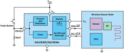
Figure 3. Integrated solution using the MAX16163
Solution Performance Comparison
The performance comparison of the two solutions depends on the duty cycle of the IoT application. For applications with a small duty cycle, the sleep current is used to measure the system efficiency when the IoT device is running, and the shutdown current is used to measure the power consumption in the shipping mode. To verify the mode of this solution, ADI selected the RTC MAX31342 with the lowest quiescent current, the battery "freshness" sealed MAX16150, and the small load switch TPS22916. The RTC is programmed using I2C communication to set the sleep time of the IoT application, and when the timer expires, the interrupt signal pulls down the PBIN pin of the MAX16150. The MAX16150 sets OUT to a high level and turns on the load switch. During sleep, only the TPS22916, MAX31342, and MAX16150 consume power from the power system.
Table 1. Current consumption of different modules in traditional solutions
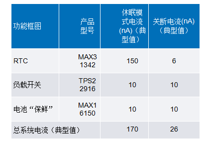
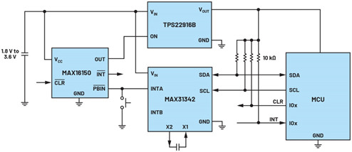
Figure 4. Discrete solution schematic
In the experiment, the battery life of two advanced solutions was evaluated at a fixed duty cycle, comparing the performance of the traditional solution and the improved solution using the MAX16163.
Battery life can be calculated using the average load current and battery capacity.
The average load current can be calculated using the system's duty cycle.


Active current refers to the system current when the wireless sensor node is active. To compare the two solutions, assume that the system wakes up every two hours, performs a specific task, and then goes into sleep mode. The system active current is 5mA. Battery life depends on the duty cycle of operation. Figure 5 shows the battery life graphs of the two solutions with different duty cycles, ranging from 0.005% to 0.015%.
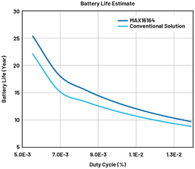
Figure 5. Battery life vs. duty cycle of a wireless sensor node
Table 2. Comparison of two different solutions

In summary, this article explores the critical role of battery power management in the context of the rapid growth of IoT devices. It shows that optimizing shipping and sleep modes is one of the best ways to improve battery efficiency . The MAX16163 solution from Analog Devices helps to control these functions more accurately in the design. Compared with traditional methods, this solution extends battery life by about 20% (for a typical duty cycle operation of 0.007%, as shown in Figure 5) and reduces the solution size to 60% of the traditional solution.
Previous article:Wanda Youshang Group launches three-phase parallel meter solution based on ST products
Next article:Zhuhai Shengsheng Micro launches MCU for multi-cell battery management using RISC-V
- Popular Resources
- Popular amplifiers
- e-Network Community and NXP launch Smart Space Building Automation Challenge
- The Internet of Things helps electric vehicle charging facilities move into the future
- Nordic Semiconductor Launches nRF54L15, nRF54L10 and nRF54L05 Next Generation Wireless SoCs
- Face detection based on camera capture video in OPENCV - Mir NXP i.MX93 development board
- The UK tests drones equipped with nervous systems: no need to frequently land for inspection
- The power of ultra-wideband: reshaping the automotive, mobile and industrial IoT experience
- STMicroelectronics launches highly adaptable and easy-to-connect dual-radio IoT module for metering and asset tracking applications
- This year, the number of IoT connections in my country is expected to exceed 3 billion
- Infineon Technologies SECORA™ Pay Bio Enhances Convenience and Trust in Contactless Biometric Payments
- LED chemical incompatibility test to see which chemicals LEDs can be used with
- Application of ARM9 hardware coprocessor on WinCE embedded motherboard
- What are the key points for selecting rotor flowmeter?
- LM317 high power charger circuit
- A brief analysis of Embest's application and development of embedded medical devices
- Single-phase RC protection circuit
- stm32 PVD programmable voltage monitor
- Introduction and measurement of edge trigger and level trigger of 51 single chip microcomputer
- Improved design of Linux system software shell protection technology
- What to do if the ABB robot protection device stops
- Learn ARM development(19)
- Learn ARM development(14)
- Learn ARM development(15)
- Analysis of the application of several common contact parts in high-voltage connectors of new energy vehicles
- Wiring harness durability test and contact voltage drop test method
- From probes to power supplies, Tektronix is leading the way in comprehensive innovation in power electronics testing
- From probes to power supplies, Tektronix is leading the way in comprehensive innovation in power electronics testing
- Sn-doped CuO nanostructure-based ethanol gas sensor for real-time drunk driving detection in vehicles
- Design considerations for automotive battery wiring harness
- Do you know all the various motors commonly used in automotive electronics?
- [RVB2601 Creative Application Development] Start to go through the development process
- Op amp output clamping mechanism and avoidance methods
- 【Development and application based on NUCLEO-F746ZG motor】11. Parameter configuration - ADC configuration
- [Solved] Why can’t I change my profile picture?
- The STM32F103VBT6 resets with a button. After releasing the button, it takes three or four seconds for the microcontroller to execute the program.
- [Xianji HPM6750 Review] + Unboxing
- C2000 combines capacitive touch and host controller functions
- "【TGF4042 Signal Generator】" High-frequency distortion measurement
- Video chip recommendation
- About MSP430 watchdog settings

 M38510/11404SPX


 京公网安备 11010802033920号