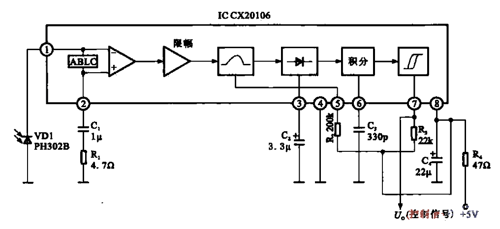
Color TV infrared remote control receiving circuit
Source: InternetPublisher:newlandmark Keywords: Infrared remote control remote control reception receiving circuit color TV Updated: 2020/02/14

The infrared remote control receiving
circuit of the TV is shown in the figure. It is
composed of an infrared receiving diode, CX 20106 preamplifier integrated circuit and peripheral components. The infrared receiving diode VDI is a PN photodiode. When there is no light, VD1 is reverse-biased and has no current;
when there is infrared light, VDI generates a photocurrent, which is input to the first pin of CX 20106. On the input impedance of the amplifier An optical signal
voltage is formed. CX 20106 is equipped with preamplifier, limiting amplification, filtering, detection and shaping circuits inside.
There is also an automatic brightness control circuit ABLC at the input end of the preamplifier circuit to prevent the input signal from being too large and overloading the amplifier. . The remote control signal emitted
from the infrared remote control circuit is a modulated 38 kHz pulse signal. This signal is detected by the VDI. After amplification and
limiting, the stray modulation interference is eliminated, and then the stronger signal is sent to the center frequency. is a 38 kHz bandpass filter.
R2 is connected to the external circuit of the bandpass filter . Adjusting the resistor value can make the center frequency of the filter change within the range of 30 to 60 kHz. The signal output by the filter is detected and
the command code pulse is obtained, and then integrated and shaped. Finally, the command code pulse is output by the ⑦ pin of CX 20106. After the instruction code pulse
is processed by the microprocessor, the corresponding execution command will be issued.
- How to Build a Simple FM Radio Receiver on a Breadboard
- Application of GaN power devices in array radar transceiver systems
- Production of a FM wireless microphone
- Change the frequency of the campus radio
- FM transmitter in a matchbox
- MICRFl03 ASK 1 GHz~800 MHz Transmitter
- GPS RF front-end circuit composed of MX2740
- DKIOOOT OOK 315 MHz Transmitter Module
- RCV420 4~20mA Precision Current Loop Receiver
- Stereo FM transmitter circuit designed with BH1417
- An infrared receiving circuit
- Automatic greeting receiving circuit
- TV sound system receiving circuit
- μPD1987C (TV) infrared remote control receiving circuit
- M50111P/AP/BP/CP (VCR, TV and audio equipment) 30-function infrared remote control receiving circuit
- BL9150 (universal) infrared remote control receiving circuit
- Philips color TV switching power supply circuit diagram
- TWH631 receiving circuit
- Using AN5132 as an image intermediate amplifier circuit for color TV sets
- Optical signal receiving circuit


 京公网安备 11010802033920号